Simulation Slashes Die-Design Time to One Month
August 1, 2010Comments
Mexican auto-parts supplier PEMSA (Pintura, Estampado y Montaje S.A.P.I. de C.V.) recently faced the challenge of designing a tandem die to build a part with a deep contoured shape. Pam-Stamp 2G software from ESI Group, Bloomfield Hills, MI, allowed the firm—in just one month—to simulate the complex stamping process, identify problems and evaluate solutions, and complete the die. Without the software, say company officials, it would have built the die, found problems, and then endured a 9- to 11-month process of fixing the die and making the required engineering changes.
Engineer Sergio Luis Cacique Borrego, responsible for designing the die to build a structural reinforcement for an automobile seat, explains that the part is made of high-strength steel and has a complex geometry that requires deep drawing. Further, the part becomes part of a spot-welded assembly and the weld area must be nearly flat.
 |
“Based on the trial results, we would have changed the design, sent the existing die to the machine shop for repairs and tried it out again on a press,” Borrego says. “It would typically take about 3 months to fix the die, but the modified die would not have produced parts that matched the original design model, so another 6 to 8 months would have been needed to implement design changes and obtain customer approval.”
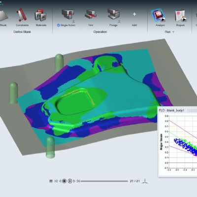
Borrego decided instead to simulate the die with Pam-Stamp 2G prior to building the tool. “The software allows us to accurately simulate the performance of complex dies,” Borrego adds. “It models the initial part and simulates all metalforming operations up to the finished product in order to forecast any potential thinning, wrinkling, twisting and springback.”
Borrego developed a four-station die for the seat reinforcement that draws the part in the first two stations, trims in the third and then trims and pierces in the fourth station. During the first forming operation, the tooling moves vertically until the final 25 mm before the die closes—then it moves at a 30-deg. angle to reduce thinning in the corners.
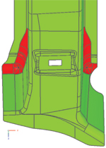
To develop the die design, Borrego exported the tool geometry of the initial die configuration into the IGES neutral file format and then imported the geometry into Pam-Stamp 2G. He then simulated the first drawing operation and discovered cracking around two small radii in the part (see photo). His first thought was to open up the radii, but realized that doing so might interfere with the weld surfaces. A series of simulation iterations allowed Borrego to determine the optimum radii without disturbing the critical weld surfaces.
ESI North America: 248/203 0642; www.esi-group.com
View Glossary of Metalforming Terms
See also: ESI North America


 Webinar