Peter Ulintz
Blank-and-Draw-Process Problems
May 1, 2017Comments
I recently received this question from a reader: We’re in the process of designing a combination blank and draw die. This is not the first time we have designed and built a die like this, but I don’t think we have been using the right formulas in the past to calculate press tonnage. On several occasions we had to move our dies to a larger press because the press we selected did not have enough power. In some cases the press slowed down noticeably during the production. When we moved the die to a larger-tonnage press the problem went away. All of our stamping machines are flywheel-drive mechanical presses. I don’t want to repeat the same mistake so I was hoping you could recommend some formula(s) to use for our tonnage calculations.
My answer: When a mechanical stamping press slows down during continuous operation, the problem generally lies with press energy, not tonnage. However, deep drawing in mechanical presses presents some unique problems related to press tonnage; thus, both topics must be addressed.
The tonnage rating of a press is the maximum load that can be exerted in continuous operation without causing damage to the machine structure or its drive system. But it is important to realize that the force available to carry out work (blanking, drawing, forming, etc.) decreases in mechanical presses as the working distance above bottom-dead-center increases. This occurs because the lever arm angle—the relationship between the crank/eccentric angle and the pitman—has reduced mechanical advantage higher up in the stroke. This commonly is referred to as de-rated tonnage. 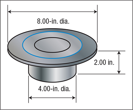
Fig. 1—Dimensions for a cylindrical cup drawn in a single-station blank-and-draw die. 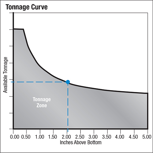
Fig. 2—Only half the rated force is available at a distance of 2 in. above bottom.
Before de-rated tonnage issues can be addressed, make sure that the blanking and drawing tonnage-calculation methods are valid. The two formulas that the reader supplied were:
Blanking = blank thickness x tensile strength x blank circumference / 2000
Drawing = blank thickness x yield strength x drawing circumference /2000
Let’s look at the blanking forces first. Although not technically correct, the formula would probably be okay to use as is. Substituting shear stress for tensile strength into the formula would provide more accurate results. But because shear-stress data are hard to acquire, the use of tensile strength will provide a margin of safety by over-predicting the required tonnage. The safety margin would also compensate for the stripping forces (about 5 percent of the punching force) that were not included in the reader’s calculations.
For illustrative purposes, let’s assume that a 4-in.-dia. cylindrical cup is drawn to a depth of 2 in. in a single-station blank-and-draw die (Fig. 1). The blank material is 0.080-in.-thick (t) mild-steel with 35,000-psi shear strength (Ss) and 56,000-psi tensile strength (Ts).
First, calculate the tonnage required to produce the 8-in.-dia. blank using the following formula:
(t x Ss x blank circumference) / 2000 lb. + stripper force
[0.080 in. x 35,000 psi x (3.14 x 8.00 in.)] / 2000 lb. + stripper force
Blanking force = 35 tons + 1.75 tons stripper force (5 percent of punch force) = 36.75 tons
Next, calculate the tonnage required to draw the cup.
For deep drawing, it is important that tensile strength be used in the calculations rather than yield stress because work-hardening continuously increases the force required to deform the blank material as it is worked. Since tensile strength can be double the yield strength—or more for some materials—the results derived using yield strength may underestimate the require drawing tonnage by a significant amount. Tensile strength will over-estimate the required force but it is a much safer number to use as a press-selection criteria.
Another component missing in the reader’s formula is the addition of a blankholder force (BHF). The assumption for BHF is generally 30 percent of the calculated drawing force. This force is significant and it must not be overlooked.
Find the drawing forces as follows:
(t x Ts x drawing circumference) / 2000 lb. + BHF
[0.080 in. x 56,000 psi x (3.14 x 4.00 in.)] /2000 + BHF
Drawing force = 28 tons + 8.4 tons BHF (30 percent of punch force) = 36.4 tons