With total travel calculated, the 20-80 rule now is applied to establish limits for installed height. Multiply total travel (2 in.) by 20 percent—0.400 in. Subtract that from the relaxed free length 3 in.)—2.6 in.
Next, add 0.400 in. to the solid height of the spring (1 in.)—1.4 in.
Therefore, for the spring to work within its optimum range, the load heights required should be applied within the installed height range of 2.60 and 1.40 in. The 20/80 rule ensures that there is ample amount of travel to engage the inactive coils initially within the design, and that the spring will not engage too closely to its solid height at its final deflection. Exceeding these parameters could potentially cause failures.
Wind Direction and Coatings
Other key factors to consider when sizing a spring: direction of wind, particularly when engineering a torsion spring, and assembly requirements. Wind direction dictates how energy is directed through the spring—right-hand (clockwise) or left-hand (counterclockwise).
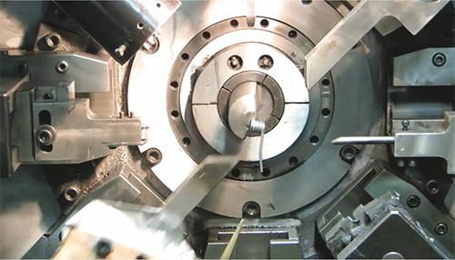
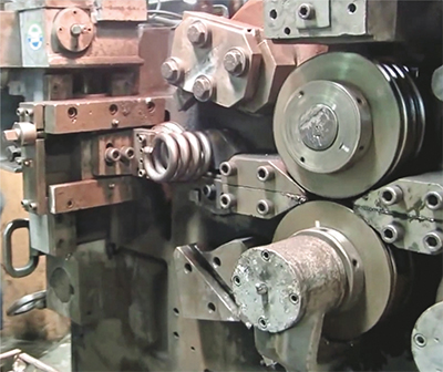
The designer also should understand how the springs will be assembled to their mating parts. When designing torsion and extensions springs, for example, an enormous assortment of end configurations can be shaped, using CNC technology, to precisely aid in the assembly process. By recognizing the spring’s complete installation requirements, the springmaker can ensure accurate assembly for crucial form and function.
Finally, with the final design complete, the manufacturer must know the specific style of coating, plating or packaging required by the end user—powder coating, zinc plating or E-coating, for example, and any bag-and-tag requests. MF
View Glossary of Metalforming Terms
See also: Ace Wire Spring & Form Co., Inc.
Technologies: Other Processes
Comments
Must be logged in to post a comment. Sign in or Create an Account
There are no comments posted. Other Processes
Bihler 4 Slide-NC Installed at Pennsylvania College of Techn...
Friday, December 1, 2023
Newcomb Spring Launches Advanced Version of its Springulator...
Tuesday, February 14, 2023
 Other Processes
Fenn Acquires MacBee Engineering
Friday, August 5, 2022
 Other Processes
Clips & Clamps Appoints Director of Customer Relations
Friday, April 8, 2022


