Peter Ulintz
The Anatomy of a Deep-Drawn Cup
September 1, 2017Comments
The engineering of deep-drawing tools relies quite heavily on data and guidelines found in die-design handbooks. These include draw-reduction ratios, blankholder pressure, forming speeds, die clearances, radii sizes and other important parameters. Previous columns have addressed draw-reduction ratios, forming speeds, and punch-and-die radii. Other data, such as die clearances and blankholder pressure, can be better understood by examining the anatomy of a deep-drawn cup.
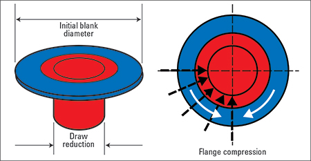 |
| Fig. 1—Flange compression in a draw reduction. |
Fig. 1 illustrates what happens when a round blank is drawn into a cylindrical cup. As the blank is drawn into the die cavity, the remaining material (flange) is compressed in the circumferential direction. As a result, large in-plane stresses build in the flange, which if not properly controlled can cause the blank to buckle or wrinkle.
A blankholder is used to control material flow by applying a restraining force to the blank surface. The blankholder must provide sufficient force to prevent buckles and wrinkle formation, but still allow the blank to flow toward the die cavity. If blankholder forces are set too high, excessive stretching and thinning can result, causing the material to rip, tear or split.
Several methods exist to determine the amount of blankholder force required in drawing operations. Best practice is to use metalforming simulations. Forming simulations allow blankholder forces to be altered until a high limit (excessive stretching) and low limit (wrinkle formation) are established. The difference between the two limits is considered the blankholder’s drawability window. The larger the window, the less sensitive the process will be to changes in holding pressure. It is important to realize that as the depth of draw increases, the drawability window narrows considerably.
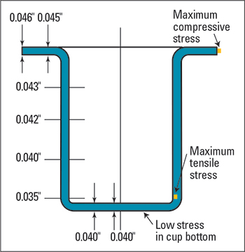 |
| Fig. 2—Thickness distributions in a drawn cup. |
At the opposite extreme, a rule of thumb assumes that blankholder pressure is approximately equal to one-third of the drawing force. Where the process falls within the blankholder’s drawability window is anyone’s guess.
Another method, falling somewhere between the other two, is to hand-calculate blankholder pressure requirements. To do this, multiply 600 lb. by the lineal inches around the draw-punch circumference (600 x pi x punch diameter) for low-carbon steels. For HSLA and stainless steels, 1800 lb. of pressure per lineal inch is commonly assumed while 400 lb. is typical for many aluminum alloys.
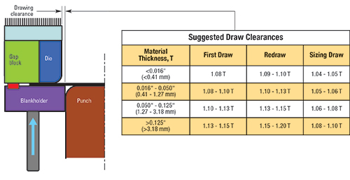
The problem of excessive blank-holder pressure can be remedied by using adjustable gap blocks, also referred to as stand-offs. Gap blocks allows higher blankholding forces without restricting material flow by providing a constant gap between the die face and the blankholder. Gap blocks are initially set at material thickness plus an additional 10 percent to accommodate material thickening due to constancy of volume in the blank.