Lou Kren Lou Kren
Senior Editor

Add AM to Your Arsenal

August 1, 2017
0
Comments


Alissa Wild is on the front lines. On a daily basis she’s witness to the continued permeation of additive manufacturing (AM) into industry, and the reluctance of some in the industry to make that leap. For some, AM is a threat to business. Can metal parts be taken from the presses, cutting machines and other metalforming equipment and instead be produced via printing? Not in the quantities and cycle times demanded by many customers, certainly not in the foreseeable future. Equipment and material costs, combined with the need for extensive post-processing to meet precision tolerances and yield acceptable surface finishes, all argue against a replacement of traditional stamping and fabricating processes. On the other hand, by shifting perspectives, AM can be viewed as an essential tool in many manufacturing operations.

Applications Everywhere

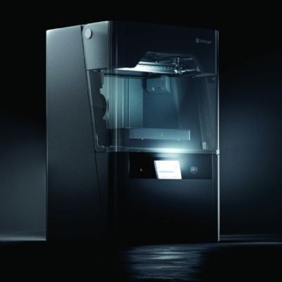
“We see a wide variety of fixturing and tooling applications in manufacturing environments,” says Wild, manufacturing aids and tooling lead for Stratasys, a maker of 3D-printing materials and equipment, and a provider of printing services. “Across industries and across facilities we see many departments—assembly, fabrication, health and safety, quality, packaging and logistics—using AM to create all different forms of nonmetallic fixturing, workholding tooling and final-use assembly tooling as well as actual metalforming tooling.”

The examples are many. Automotive OEMs and their tier suppliers use fused deposition modeling (FDM, an AM process where filament is heated to a molten state and deposited in layers to build a part) to produce assembly fixtures. The U.S. Navy’s repair facilities, Fleet Readiness Centers including FRC East and FRC West, actually use FDM tooling when forming limited-quantity parts in runs from one to 500. End-of arm robotic tooling is another common application noted by Wild.

When Time is the Enemy

Time savings is a big factor when deciding to implement AM, according to Wild.

“FDM tooling helps speed the assembly process in the manufacturing environment,” she says. “In other cases, if tooling is out for repair or if a manufacturer is waiting on new metal tooling, it can supplement with FDM tooling. AM fits well whether it’s production tooling or as a bridge tool when waiting for permanent tooling. AM is a time saver, cutting the acquisition process from weeks to days, which is a game changer for getting your manufacturing floor up and running. And, in response to a manufacturing problem, obtaining tooling the same day or the next day brings a real competitive advantage for many manufacturers.”

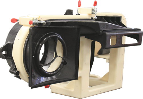
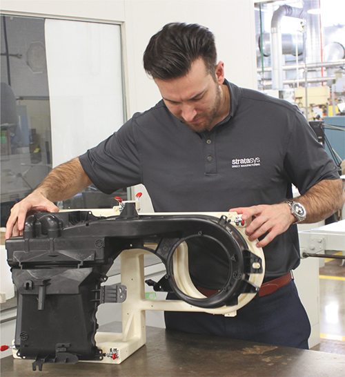
This large inspection tool, more than 3 ft. long and made from thermoplastic material, was designed, printed and delivered to an automotive supplier within one week—a fraction of the time as would be required for a traditional metal tool.

For end-of-arm robotic tooling, in some cases, FDM tooling can be a one-to-one replacement, which is true in other workholding applications as well.

“If you are simply using a nest or cradle to hold a part during a particular operation, an AM-created part may replace the traditional machined resin block,” says Wild. “You may even be able to use the same CAD design.

“Obviously, AM has differing design rules,” she continues, “but the beauty of additive is that design complexity comes free—there is no added cost. AM offers the advantage of incorporating added features and consolidating components in a fixture design. It depends on the application, but starting with the same CAD file, we may be able to consolidate 30 components down to one or two.”

In these cases, AM can help produce what Wild calls “hybrid fixtures,” which include, for example, hard contact points for a drill guide.

“The fixture shape will be the same, but metal inserts are placed into the fixture component to address durability and wear concerns,” she says. “The CAD process for producing the ideal fixture in AM is very similar to traditional CAD design, but incorporates the freedom and complexity that comes along with designing for additive, where design is not constrained by the limitations of machining and other traditional subtractive processes. The key is learning AM design rules. Just as injection molding and five-axis machining have design rules, so, too, does AM.”

Don’t Wait for the Pain Point

Experiencing a pain point typically signifies the entrance of manufacturers into the AM realm, according to Wild.
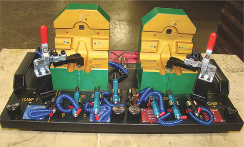
A check tool for stamped automotive seat brackets required a lifetime of 42,000 inspections. The previous tool, constructed via traditional subtractive-manufacturing processes, weighed more than 40 lb. The redesigned thermoplastic 3D-printed tool weighs only 4 lb., with delivery time cut from six to two weeks. Its user reports that the smaller-profile tool enables improved part alignment.

“Such a point may be if the manufacturer needs a tool or fixture in a hurry and the traditional routes take too long or are too costly,” she says. “A traditional fixture or tool had never existed or was cost-prohibitive…these experiences often open the door to exploring AM.”

The best time to explore AM is prior to having to respond to these pain points, when more thorough research can be performed. In doing such research, you may find all sorts of potential AM applications in your operation.

“We’ve seen it in automotive companies, starting with a safety or ergonomics issue where someone has to lift a tool off of a shelf and carry it back and forth to a workstation two or three times a day,” says Wild.

Fixture Examples Abound

In one case, relays Wild, Solaxis Ingenious Manufacturing in Bromont, Canada, using Fortus 3D printers from Stratasys, designed and manufactured a jig for an automotive supplier, which uses it to assemble high-volume door components. After developing several iterations of the jig, Solaxis not only was able to produce a 3D-printed jig that is more than 100 lb. lighter than a typical jig for this application (the 3D-printed jig weighs 28 lb.), but it also slashed design and manufacturing time by at least two-thirds as compared with traditional methods, according to Solaxis officials.

“No longer is a crane operation needed nor another person needed to spot the jig,” says Wild, “so the burden rate of that tool is reduced.”

Another example: TS Tech, in supporting its stamping operations, switched to 3D printing to produce a seat-bracket check tool. Stratasys Direct Manufacturing redesigned and produced the tool, which featured a weight reduction from 40 to 4 lb. with a production-time reduction from six to two weeks. The new tool not only had a smaller profile, but it provided better part alignment and was easier to transport than the inspection tool it replaced. And, report TS Tech officials, it was tough enough to withstand the needed 42,000-inspections lifetime.

Oreck Manufacturing, according to Wild, is another convert to 3D printing, using the process to create custom assembly fixtures for its high-end commercial vacuum cleaners. According to Oreck’s senior model maker, the company has reduced fixture-production costs by 65 percent by using its inhouse FDM 3D printers. Oreck has used AM to make hundreds of inspection fixtures for its CMMs. On average, it saves $200 and 6.5 days versus having them machined.

Conference: 3D Printing for Jigs, Fixtures and Prototypes

Join the Precision Metalforming Association and MetalForming magazine on September 7 in Cleveland, OH, for a day of presentations on what metalformers and fabricators need to know about 3D printing for jigs, fixtures and prototypes.

3D printing allows for customization of end-of-arm and workholding tooling and devices, test-fixture components, and more. Unlike conventional manufacturing, 3D printing handles design complexity with ease, and without adding cost or time. And, the flexibility of 3D printing allows metalformers and fabricators to readily optimize their products to perform specific tasks. Join us for this informative day of presentations, and come away with a deep understanding of the various types of printing processes, materials and techniques you can use to improve your design and production of jigs, fixtures and prototypes.

Schedule and Presentations

8:00 a.m. – Registration and complimentary continental breakfast

8:45 a.m. – Keynote: Use of 3D Printing in Manufacturing, Dr. Jim McGuffin-Cawley, Case Western Reserve University

9:30 a.m. – 3D Opportunities in Tooling: Additive Manufacturing Shapes the Future, Ian Wing, manager, Deloitte Consulting Strategy & Operations

10:15 a.m. – Break

10:30 a.m. – Printer’s Dilemma—Managing Tradeoffs between Cost, Quality and Speed in Additive Manufacturing, Ron Weavil, North American sales manager, 3D Platform

11:15 a.m. – New Materials/Polymers for Printing Fixtures, Tooling and Prototypes, Matthew L. Schmidt, additive manufacturing manager, rp+m

12:00 p.m. – Lunch

1:15 p.m. – Case Study: Caterpillar Additive Manufacturing Factory and Its Long-Term Commitment to Additive Manufacturing, Stacey DelVecchio, AM product manager, Caterpillar AM Factory

2:30 p.m. – Case Studies with Metalformers and Roundtable Discussion, Clips & Clamps, Zierick Manufacturing, Dayton Rogers, OGS Industries

3:45 p.m. – Adjourn

Cost of attendance is $199 for PMA members and $399 for nonmembers. Out-of-town attendees are encouraged to take advantage of a special PMA guest rate at the Holiday Inn Cleveland-South Independence, including complimentary shuttle to and from Cleveland Hopkins International Airport and to and from PMA for the program. To register, visit www.metalformingmagazine.com/3dtooling. For questions related to registration or program specifics, contact Marlene O’Brien at mobrien@pma.org or 216/901-8800. Sponsors can contact Brad Kuvin at
bkuvin@pma.org or 216/901-8800.

Before employing AM, Oreck took 30 days to complete its first-article inspections of 20 to 30 components for a new product. After receiving the first samples from production tooling, the QA department would start making fixtures and programming the coordinate measuring machine (CMM). On the 30th day, it would complete the CMM inspection and release the program to the production floor. With inhouse 3D printing, the company can quickly begin producing fixtures via its 3D printers and begin CMM programming when a tooling order is released, not after samples are received. As a result, the Quality Assurance department is ready and waiting for the arrival of the first samples. The company estimates that it can save $100,000 to $500,000 annually in such wait-time reductions.

Rapid Tool-Up for Metalforming

Nonmetal AM has proven successful not only as a method to manufacture jigs and fixtures, but for metalforming tools as well. This often happens when metalformers need to prove out tooling, can’t wait for traditional tool-build methods or see the benefits of economical low-volume production.

Hydroforming and stretchforming, notes Wild, are two proven applications for tooling, including punches, pressure intensifiers, matched male and female tools, and back-filled tools. In tests by Stratasys with industry partners, Wild reports success in using Ultem 9085 or Nylon 12CF on Stratasys Fortus 3D-printing systems to produce low-volume or bridge tooling in forming applications. These tools, she says, have been validated for forming pressures to 15 ksi in runs to 100-plus parts.

FDM was used to produce a 10 by 13 by 2.5-in. stretchforming tool with multiple contours, made with Ultem 9085 material. The tool, according to Wild, successfully formed an aluminum alloy, 2024-0, in thicknesses from 0.050 to 0.100 in. This is an optimal application, she says, because surface pressures are minimal, and the tool can be easily optimized to minimize build times and cost.

The same material with FDM was employed to produce insert tooling in a tube-hydroforming application. With internal pressure ranging from 3 to 15 ksi, the tooling formed 16-gauge 1008 carbon steel, as a 2-in.-dia. tube, in 13 forming cycles. This tooling is best-suited for minimal-deformation operations, reports Wild. High-deformation operations would require consideration of localized stress concentrations.

And, for rapid repairs, The U.S. Navy has employed the FDM AM process to produce a variety of simple polycarbonate forming tools. Navy officials say the process has allowed for the return of aircraft to service (after part fractures due to hard carrier landings, for example) in a fraction of the time as compared to traditional tool-and-part-production processes.

Again, across all of these examples, printed tooling yields significant lead-time savings as well as customized and economical low-volume production. Important factors to consider when researching the resin-tooling route: forming pressures, quantity of parts needed and type/thickness of the metal to be formed.

Taking the Next Step

Okay, so all of the above has convinced you that AM can serve valuable functions in your operations. What now?


“The AM landscape is dotted with organizations to help you travel the 3D-printing path,” says Wild. “An example is Stratasys’ Expert Services Group, which can create CAD designs and perform other services. It can take your file of a fixture or tool, redesign it for AM and even build it while walking you through the entire process. Service bureaus also can build fixtures and tools that you design if you have that capability (Stratasys Direct Manufacturing offers this service).

Whichever route you choose, Wild offers some questions to serve as guidelines:

  • Where and how is the tool/fixture used?
  • What are the critical tool/fixture features and functions?
  • Are there temperature requirements?
  • Will the tool/fixture be in the presence of chemicals and solvents?
  • Answers to these questions provide guidance on the proper materials and build processes to employ.

Theoretically, AM fixtures and tooling are not limited by size. Even though printers may have build chambers measuring 3 by 2 by 3 ft., by sectioning and then bonding the sections together, much larger fixtures and tools can be constructed. Wild notes that, through sectioning and bonding, Stratasys has produced forming tools surpassing 8 ft. in length. But, she cautions, the limiting factor is accuracy.

“Very large tools that require high accuracy will need post-process machining,” she says. “Critical surfaces must be machined to meet the tighter tolerances that AM can’t meet right out of the machine. There are ways to mitigate accuracy concerns using design and build operations as well as machining.”

AM Can Be Your Friend

The goal of this article was to provide insight into AM, and how it can be a friend to metalformers, fabricators, and tool designers and builders. With a discerning eye and some knowledge of the process, my bet is that you readily can find AM applications in your operations. You’ll be surprised by how much AM can help…and in unexpected ways, as this last example illustrates.

At a recent aerospace conference, a speaker from a major defense contractor relayed how his company began using AM to produce jigs and fixtures to test large aircraft parts. The company had bought a new resin 3D-printing system with a huge build envelope such as one used to print automobiles. The machine was installed in an otherwise empty room and the engineers got right to work deciding what to make. One of them noticed that everyone was standing, as the room had no furniture. The first product they designed and built? A chair. MF

Industry-Related Terms: Aluminum Alloy, CAD, Carbon Steel, Case, Fixture, Forming, Insert, Jig, Lines, Model, Point, Surface
View Glossary of Metalforming Terms


See also: Stratasys, Inc.

Technologies: Additive Manufacturing, Other Processes

Comments

Must be logged in to post a comment.
There are no comments posted.

Subscribe to the Newsletter

Start receiving newsletters.