 Chris Baur
Programming for 3D Laser Cutting
April 1, 2016Comments
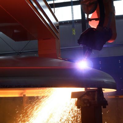
The laser is a fascinating tool that has been used in manufacturing for decades. Whether the application is cutting, welding, marking or metal deposition, all laser processing requires delivery of the beam to the part. Depending on the part and application, there are various ways to achieve this. For laser cutting, the shape of the part impacts how the beam is delivered. The part might be a simple 2D shape with all of its features in a single plane, or it might be a complex 3D form with angled surfaces and directional changes to its surfaces.
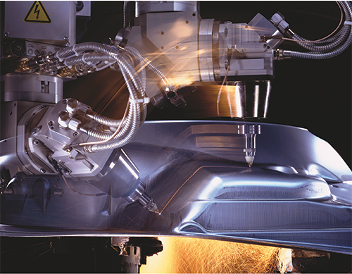 |
| Complex 3D cutting directs the laser beam over angled surfaces and requires countless directional changes. The process requires a five- or six-axis motion system, and with each additional axis comes increased programming complexity. |
While the laser-cutting process differs little during 2D or 3D cutting, the motion systems used to deliver the beam differ considerably. When cutting simple 2D shapes in flat sheetmetal using a 2D cutting machine, a two-, 2.5- or three-axis motion system gets the call. When laser cutting 3D parts, the motion system must include an additional two or three axes—a five-axis gantry-style machine or a six-axis robot gain favor.
While each additional axis comes with increased programming complexity, state-of-the-art laser-cutting machines feature advanced control systems and software that allow for more user-friendly programming than with previous generations of machines. To take advantage of these tools, programmers simply need a moderate understanding of the programming considerations for multiaxis laser cutting. That education begins with a comparison of programming for 2D versus 3D.
Programming for 2D Parts
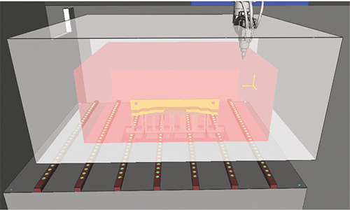 |
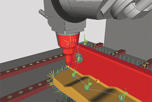
| Fig. 1—The programmer’s list of tasks includes locating the part’s CAD file within the work envelope of the machine, properly placing the part on its fixture within the 3D working envelope, represented here as a pink box. |
Regardless of the 2D laser-cutting machine and software program used, an operator generally has the following goal: cut as many quality parts as quickly as possible, using as little material as possible and without causing damage to the laser system or its components.
Material utilization often is the highest priority in 2D processing, as hundreds of individual parts or dozens of unique part numbers might come from one sheet of raw material. Most software options offer and focus on nesting solutions to maximize yield. The best programs offer additional support, such as routines that will minimize the damage caused by the nozzle collisions that can occur if the cutting head contacts the sheet or a tipped part. Since the cutting head can only approach the sheet from above with a 2D laser-cutting machine, the possible collision areas are minimal. Also, a skilled programmer can easily add microtabs to keep parts in place and prevent tipping, or sequence the cutting path in the nest to accommodate parts that are likely to tip. However, when processing 3D parts on a multiaxis machine, the potential for collision increases significantly.
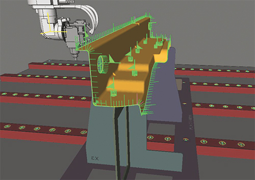 |
| Fig. 2—To program cutting contours, which can include interior hole features, external trims, simple shapes or extremely complex geometries, the software calculates and displays the surface perpendicularities around the desired contours, shown as vectors (the green lines). |
Production for 3D Parts
The main objective of any laser-cutting software is to allow a fabricator to move from offline programming to real production as seamlessly as possible. Processing 3D parts, as compared to 2D parts, becomes more complex. Thankfully, by following a simple process programmers can make a fluid transition from 2D to 3D programming.
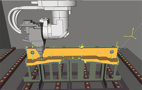
First, the programmer should ensure that the fixture and part CAD files contain all of the features the operator will experience in production. The file should be as detailed as possible, including references accommodation for any clamps, hoses and other elements that the cutting head may encounter during fabrication. Any omitted features in the CAD system could be a source of collision during laser processing. Be sure to model clamps in their open and closed positions within the CAD model.
 |
| Fig. 3—Since vectors initially are programmed perpendicular to the part surface, head or nozzle collision can exist in internal corners. To account for this, the laser head must be manipulated, typically at an angle to 15 deg., in these areas to create cutting-head clearance. |
Ideally, the programmer should generate three models, used together: a raw part model, a finished part model and a fixture model. Without a raw blank part file, the programmed cutting path may still contain areas where cutting-head or nozzle collisions may occur. Remember that even the best CAD file may not precisely represent the actual part. Manufacturing tolerances and variations can occur and always are a factor during laser cutting. To compensate for these variations in the manufacturing process, many 3D-cutting machines feature height-sensing capabilities (Trumpf calls this feature ControlLine). Here, capacitive sensing technology works to maintain a constant distance between the cutting nozzle and the workpiece, minimizing or avoiding collisions and their resulting damage.
 |
| Fig. 4—With all collision areas eliminated and the NC program optimized (shown here), the programmer must then locate a “zero-point” on the part or fixture. He uses this for locating the part in the machine. |
Once the programmer has gathered all of the necessary CAD data and is ready to program the 3D part, he then must locate the part’s CAD file within the work envelope of the machine, properly placing the part on its fixture and within the 3D working envelope (Fig. 1—the pink box represents the work envelope of the five-axis machine). After locating the part, he then identifies the cutting contours, which can include interior hole features, external trims, simple shapes or extremely complex geometries. The software will calculate and display the surface perpendicularities around the desired contours, shown as vectors (shown as green lines in Fig. 2). If a programmer needs to program a cut that is not perpendicular to the surface—a bevel cut for example—he can modify the vectors individually, in segments or along the entire contour to the desired cutting angle.