Most commercial IDT units employ direct-drive designs and thus use a preloaded mechanical spring as a motion-absorbing safety system to protect the tapping unit from damage in the event of a strip short-feed or a broken punch. If the workpiece contacts the tap before the start of the tapping cycle, premature wear can occur on the tap and also within the tap control cartridge or pitch insert. Further, the first thread produced in the part can become damaged due to the tap reverse-skidding against it during retraction as the misfeed spring unloads while the tap exits the hole.
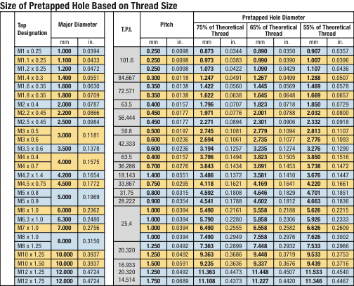
Workpiece control/size of pretapped hole: Recommended prehole diameters for rollforming taps differ from those for conventional cutting taps (i.e., tap drill charts). As an ideal starting point for achieving a good balance between quality rollformed threads and optimized tap life, use 65 percent of the theoretical full thread. Attempting to form more than 75 percent of theoretical full thread is never recommended and will not produce any additional thread strength (Fig. 1). The substantive rigidity of a rollformed thread’s crosssection comes from its pyramidal base, not the geometry near its crest. In the case of the ever-popular M6 x 1.0 size, decreasing the prehole diameter from 5.56 mm to 5.50 mm can nearly double the required dynamic tapping.
Two key points: A 5.56-mm extrusion punch will not actually produce a 5.56-mm hole. In fact, the resulting diameter will be slightly smaller due to material memory or elasticity, so a bit of tribal knowledge (or perhaps trial-and-error experimentation) may come in handy in smartly arriving at a particular desired prehole diameter.
Second, as the pierce punch or extrusion punch wears, the prehole diameter gradually shrinks. Continuous monitoring of the diameter, whether by periodic manual verification using hard gauges or by a more sophisticated hot-pilot sensoring approach, proves helpful in maintaining consistent thread quality and optimizing tap life.
Prehole shape/geometry: The pretapped hole should be uniformly cylindrical and free of any burrs or aberrations. With certain materials, particularly stainless steels, the stamper may need to pierce or extrude the hole to a slightly undersized diameter and then shave a material in a subsequent die station to bring the hole precisely to the desired diameter and cylindricity. Shaving operations also can serve to remove the thin work-hardened layer of material near the surface, reduce the required tapping torque, extend tap life and produce better-quality threads.
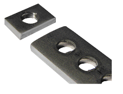 |
| Fig. 2—The pretapped hole should be uniformly cylindrical and free of any burrs or aberrations. With certain materials, particularly stainless steels (shown here), the stamper may need to pierce or extrude the hole to a slightly undersized diameter and then shave a material in a subsequent die station to bring the hole precisely to the desired diameter and cylindricity. |
 |
| Fig. 3—The nature of rollforming threads causes a small material pucker at the ends of the thread where the thread terminates at the top and bottom faces of the material. |
Consider the Type 304 stainless-steel application example shown in Fig. 2. The prehole was produced in a single die progression (tap size = M8 x 1.25, prehole diameter = 0.294 in., material thickness = 0.156 in.). Note the ragged hole geometry and the heavy burrs present on the material fracture side.
Coining/chamfering a hole before tapping: The nature of rollforming threads causes a small material pucker at the ends of the thread where the thread terminates at the top and bottom faces of the material (Fig. 3). This is normal. In the case of an extruded hole, this puckering effect also occurs at the exit or rough end of the extrusion, but its presence there is usually inconsequential. When the finished piece must be mated flush against another part in a subassembly, this material pucker often can present problems. If the pucker gets pushed back into the thread space, it usually causes binding issues once the fastener is introduced.
To avoid binding, some designers will instinctively chamfer the prehole by adding a coining operation just prior to tapping. However, material pucker will still occur, although it now will sit in the chamfered depression below the top surface of the part and create problems should the tap be required to enter the part on the side where the chamfer was installed. Here, particularly with higher grade carbon steels and stainless steels, it can be difficult for the tap to readily engage the part. The material becomes work-hardened in the chamfered region, and the angle of the chamfer somewhat mimics the angle on the forming lobes of the tap. So, the first lead of the tap prefers to skid against the hole’s opening rather than readily bite into it.
Again, most commercial IDT designs incorporate a spring-loaded misfeed-protection system, and trying to tap into such chamfers often can result in unintended, partial misfeed-system actuation. This means usable revolutions for the tapping work are lost, and an incomplete thread typically results. A better approach—when possible—is to provide the necessary clearance for the material pucker by coining a slight recess into the adjoining part, which carries no thread.
Minimize (or eliminate) lateral and vertical movement of the part relative to the tap while the tap is engaged: Although most commercially available IDT systems can accommodate slight tap-to-hole misalignment, it’s important to ensure the workpiece cannot shift during the tapping process. A robust piloting and clamping arrangement is mandatory for reliable IDT operation and satisfactory tap life. With stripper-mounted IDT configurations, the stripper should be precision guided to the lower die through the use of pins and bushings, locating cones, or both.
If the strip moves vertically during the tapping process, the tap can be forcibly pulled out of the tap holder, or the working end can fracture and be separated from the rest of the tap, or both.
Lubrication (tap): Rollform tapping is a high-friction process, and so lubrication must be provided.
 |
| Fig. 4—Ideally, particularly with HSLA and stainless steels, the setup will spray the tapping lube onto the end of the tap and into the pretapped hole, from the opposite side from which the tap is traveling. |
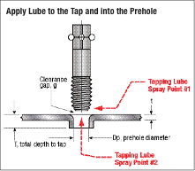
Delivery point: Lubricant/coolant must be delivered to the working portion of the tap (first three to five leads), on every press cycle. Simply spraying or flooding the strip is wasteful and insufficient, because the lubricant doesn’t get applied where it’s needed—on the tap and in the prehole. Larger taps (M10 or 3⁄8 in. and above) should be serviced by two or more spray nozzles. Ideally, particularly with HSLA and stainless steels, the setup will spray the tapping lube onto the end of the tap and into the pretapped hole, from the opposite side from which the tap is traveling (Fig. 4).
Lubricity/quality: A discussion of this very subjective topic is well beyond the scope of this article but, suffice to say a near-dizzying array of petroleum-based and water-soluble commercial lubricants are available in the marketplace. Strict adherence to the lube manufacturer’s guidelines (dispensed amount, mix ratio, recommended delivery method, etc.) is strongly advised. Experimentation with various lubricants may be necessary to optimize tap life, particularly with HSLA and stainless steels.
Quantity required: The amount of lubricant required depends on tap size, material type, lubricant type and mix ratio. Some experimentation and bench-marking may be required to determine the proper amount of tapping fluid to be administered for each press cycle.
Preventive Maintenance
As previously discussed, monitoring and controlling prehole diameter and shape will help enable an effective preventive-maintenance program for IDT installations. IDT devices are high-speed, high-precision mechanisms and should be periodically cleaned and lubricated in accordance with the manufacturer’s recommendations.
Die protection/sensoring: Physically detecting the tap’s successful penetration through the workpiece is an important step in striving for zero-defect IDT. Inductive proximity sensors, photoelectric/optical sensors or physical contact switches may find use, according to the end-user’s preference. Turn the sensoring equipment to “look on” for the tap’s presence generally around bottom-of-stroke, between 180 to 190 deg. after top-dead center. A good tap sensing setup can detect broken or worn taps (when partial misfeed-system actuation is involved), as well as improper tap-setup positions at initial tryout and each successive production startup.
Optimizing Tap Life
Tap life: A common—and difficult-to-answer—question from IDT users is, “What kind of tap life can I expect in this application?” Material type, tap size and depth, press speed and stroke, the amount of press stroke used for tapping, prehole diameter, tap coating, and the type and quantity of tap lube all affect tap life. For IDT manufacturers, it’s generally safer to answer such questions with actual case-study data.
With a new application, it’s advisable to optimize and maintain the key parameters and then benchmark the resulting tap life. In healthy IDT applications, taps generally will wear out before they break. In one mode of wear, the tap continues to fully penetrate the part, but the forming lobes become so worn they’re no longer producing a deep enough thread (major diameter), and the “go” side of a pitch-diameter thread gauge no longer will go through the part.
Another a tap can wear out: The lead-in threads become too dull to immediately engage the prehole, and a partial actuation of the misfeed spring (safety system) occurs while the tap struggles to enter the hole. As the tap skids against the hole opening, the safety system’s misfeed spring compresses and its preload increases. Eventually, a sufficient amount of preload develops and the tap finally engages the part and begins to form a thread. However, in such cases the tap invariably loses useful revolutions upon entry and, in so doing, usually falls short of tapping the part completely to depth.
Watch the Speed Limit
Speed restrictions with IDT technology almost als result from the physical limitations of the taps, rather than the IDT units themselves. These limitations are mandated by the amount of friction-generated heat that can be tolerated by the tap’s base material and coating, and the lubricant being applied. So, the next time you’re hoping to go 60 strokes/min. in an M10 x 1.50 stainless-steel application, don’t blame your IDT supplier when it tells you it can’t be done.
 |
|
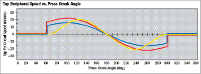
Fig. 5—Graph illustrates peripheral tap speeds (while the tap is engaged in the material) for three different IDT alternatives for a stainless-steel application. Red and blue curves give speed profiles for direct-drive and external drivescrew IDT devices, while the yellow curve represents the speed profile for a cam-actuated internal drivescrew IDT device.
|
Fig. 5 shows peripheral tap speeds for three different IDT alternatives for a stainless-steel application. Each of the three curves represents the peripheral speed while the tap is engaged in the material. The red and blue curves give speed profiles for direct-drive and external drivescrew IDT devices, while the yellow curve represents the speed profile for a cam-actuated internal drivescrew IDT device. Because direct-drive designs generally do not disengage from the upper die shoe during operation, the tap moves continuously whenever the press operates. Thus, the tap has significant velocity when it’s trying to engage the hole.
By contrast, cam-actuated IDT devices are engaged and disengaged by the upper die shoe during the press cycle. The tap gradually accelerates from rest and exhibits a low velocity upon entry into the prehole—the single most critical moment in an IDT operation. In the case of the red curve, the peripheral speed of the tap upon entry is about 16 m/min. In the case of the blue curve, the peripheral speed is about 12 m/min. In the case of the yellow curve, the tap peripheral speed is very slow upon entry into the workpiece, which generally makes for more reliable engagement and reduced tap wear rates.
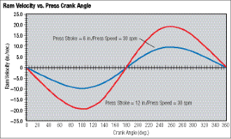 |
Fig. 6—Choose the shortest press stroke available. The press stroke, of course, must be greater than the tapping stroke and must allow sufficient time for feeding and piloting.
|
How to Maximize Speed
Key points in maximizing the speed of an IDT application:
- Understand and respect the kinematics of the process. Design and build the die around the necessary operating parameters of the IDT unit.
- Use the longest tapping stroke possible. Not to be confused with depth to tap, tapping stroke is the amount of press stroke that can be safely used to tap.
- Match stripper travel (and piloting duration) to the tapping stroke.
- Choose the shortest press stroke available. The press stroke, of course, must be greater than the tapping stroke and must allow sufficient time for feeding and piloting. A 12-in.-stroke press operating at 30 strokes/min. will exhibit double the ram velocity of a 6-in.-stroke press operating at 30 strokes/min. (Fig. 6).
- Maintain the prehole at a diameter that corresponds to 65 percent of theoretical full thread.
- Provide ample, quality tap lubrication, delivered directly to the first three to five leads of the tap on each and every press cycle.
How to Handle HSLA and Stainless Steels
When stamping high-strength alloys, the challenge of producing a quality prehole that is uniform in size and shape increases due to the strain-hardening nature of these materials. In most cases, at least one shaving operation is needed after the hole has been initially formed.
Compared to a cold-rolled-steel application, the allowable tap peripheral speed with HSLA is about half, and with stainless steel it’s about one third.MF
Industry-Related Terms: Alloys,
CAD,
Case,
Center,
CNC,
Coining,
Die,
Extruded Hole,
Form,
Forming,
Gauge,
Insert,
Layer,
Penetration,
Point,
Ram,
Stainless Steel,
Stripper,
Stroke,
Surface,
Tapping,
Thickness,
TorqueView Glossary of Metalforming Terms
See also: DAYTON Lamina Corporation
Technologies: In-Die Operations, Tooling


 Ray Osborne
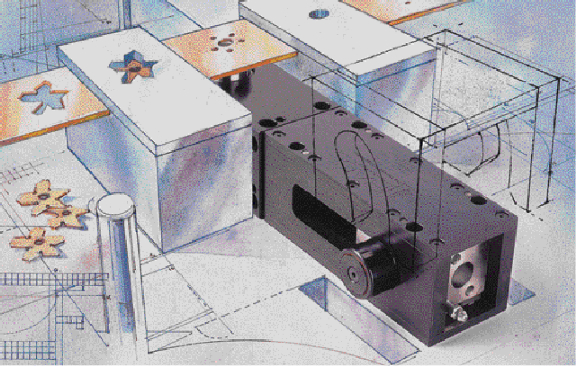 Although it’s possible to drive an IDT application by several different auxiliary-power approaches, including servo-mechanical and hydraulic, here we’ll focus on mechanically driven IDT designs. The very same fundamentals and principles that apply to rock-solid die design, reliable die construction and trouble-free die operation also apply to attaining success (and handsome profits) with IDT. So, let this article serve to debunk the myth and mystery of IDT once and for all.