There are different requirements for failure by fracture. Here, the necessary strains must exceed the fracture limit only at one portion of the sheet thickness. The highest strains still occur at the outer surface of bends or at cut edges, creating likely fracture-initiation sites. Once a microcrack forms, additional deformation or energy will cause it to grow to the point of failure. So, while fracture strains still exceed necking strains, in AHSS grades the gap is smaller than with conventional steels, with the triggering mechanism easier to attain (Fig. 1).
Researchers typically describe these differences as either global or local formability. Global formability characterizes the resistance to necking, important when deformation occurs in the presence of a relatively large and uniform strain field. Local formability refers to fracture resistance in response to deformation concentrated within small and localized regions.
Automotive AHSS Grades: Microstructure Matters
 Most conventional steels used in automotive applications have a uniform distribution of a single metallurgical phase called ferrite. While high-strength low-alloy (HSLA) steels rely on precipitation-strengthened ferrite as their primary microstructural component, AHSS grades rely on the full spectrum of different phases in varying amounts and distributions associated with the specific type and strength level of that particular grade. These phases include soft ferrite as well as martensite, bainite and austenite.
Dual-phase (DP) steels, the workhorse of the automotive AHSS grades, have a microstructure of hard martensite surrounded by a matrix of soft ferrite. Another AHSS grade, transformation-induced-plasticity or TRIP steels, also have soft ferrite and hard martensite as microstructural components, along with retained austenite and bainite.
This microstructural balance provides these grades with both high strength and high elongation, but also causes poor edge-stretching performance. The high hardness difference between ferrite and martensite leads to the formation of microscopic voids at the interface between the phases. Shearing to produce cut edges further damages the microstructure, with the shearing process work hardening the steel sheet at the edges. When these edges experience tensile stress—during stretch flanging or hole extrusion for example—these voids combine to form cracks. Therefore, these grades may not be the best choice for engineered parts with expanded cut edges.
Fortunately, other options exist. For example, some steel companies offer DP grades with modified compositions and mill processing to increase yield strength while maintaining tensile strength. Metallurgically accomplished by increasing the strength of the ferrite, the microstructural components now have a less-extreme difference in hardness. This hardness uniformity holds the key to achieving higher stretched-edge flangeability, and explains why single-phase martensite provides reasonable edge ductility despite having high yield and tensile strength (Fig. 2).
Complex-phase (CP) steels represent another option for providing good edge ductility at high strength. The microstructure of CP grades consists of martensite and retained austenite in a ferrite-bainite matrix, but unlike with DP and TRIP steels, the ferrite in CP steels is fine-grained and precipitation strengthened, resulting in a high-hardness ferrite. Bainite is a high-strength phase but with a lower hardness than martensite. Again, with relatively uniform hardness distribution of the metallurgical phases, CP steels possess good sheared-edge ductility.
Impact of Edge Condition
To quantify a material’s edge-stretching ability, we call on the hole-expansion test. After creating a hole of known diameter, a punch with specific dimensions expands that hole until an edge crack ends the test. The hole-expansion ratio represents the percent expansion of the initial hole diameter.
The international standard ISO 16630, “Metallic materials—Sheet and strip—Hole expanding test,” specifies several test parameters, including a 10-mm initial hole diameter created by shearing with a 12-percent clearance, and expanded with a conical punch with a 60-deg. apex angle. Locking in these values creates a way to compare performance between grades and suppliers. Larger initial-hole diameter appears to be associated with reduced hole expansion, and 12-percent clearance may not be the best choice to optimize edge stretchability.
For nearly 50 years, practitioners have known that a machined hole results in the best hole expansion—as much as three times that of a hole punched with 10-percent clearance. This results from the lack of a work-hardened shear-affected zone around the hole circumference. Other approaches that result in minimal edge work hardening, such as laser or waterjet cutting, also fall into this category. However, this information is difficult to put into practice, since punching holes remain the standard approach used in high-volume operations.
Historically, 10-percent punch-to-die clearance has been the rule of thumb used throughout the world. For mild and HSLA steels, this produces sufficient results since these grades have decent edge stretchability. With AHSS grades, however, the influence of punching clearance deserves greater attention.
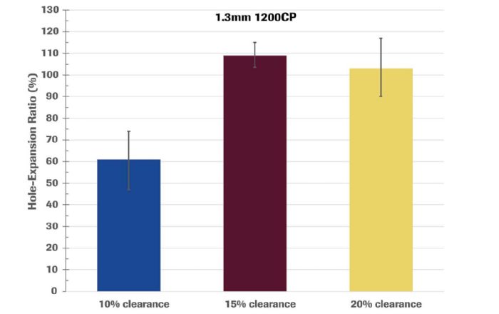
Researchers have determined that thicker steels require greater clearance, with some recommending an extra 1-percent clearance for each additional 0.5 mm in thickness. Other sources suggest that optimized performance occurs at 15- to 18-percent clearance, depending on the strength, thickness and microstructure. For example, Fig. 3 highlights the effect of cutting clearance on a CP steel with 1200-MPa tensile strength and reinforces that the historical rule-of-thumb guidance of 10-percent clearance does not apply for all grades. Increasing the clearance to 15 percent leads to a significant improvement in hole expansion. And while the HER resulting from a 20-percent clearance was substantially better than that from a 10-percent clearance, it was not as good as from a 15-percent clearance. Importantly, these differences do not appear when testing only to the requirements of ISO 16630, which specifies the use of 12-percent clearance.
Prediction Difficulties
Again, most forming-simulation software does a great job predicting locations at risk for necking failure, as researchers understand the mechanism for necking failure and the software incorporates the mathematical expressions of these mechanisms. However, substantially more challenges exist when predicting edge-cracking failures. Among them: mathematically defining the interplay between the damage from shearing on the microstructural components, which varies by type and distribution in each grade, and sometimes from each supplier. Isolating the effects from other variables, such as punch-tool sharpness, shearing angle and tool coating, only enhances the difficulty in defining the mathematical relationships.
Even in the face of these challenges, advanced models have begun to incorporate the necessary tools to capture these many variables, ultimately leading toward improvements in simulation accuracy of all failure modes.
Note: The images included here are based on content presented at www.AHSSinsights.org; visit that site for information and forming/joining best practices related to AHSS. MF
Industry-Related Terms: Austenite,
Bend Radius,
Draw,
Ductility,
Edge,
Form,
Forming,
LASER,
Martensite,
Point,
Shearing,
Spectrum,
Surface,
Tensile Strength,
Thickness,
Work HardeningView Glossary of Metalforming Terms
See also: Engineering Quality Solutions, Inc., 4M Partners, LLC
Technologies: Materials


 Daniel Schaeffler
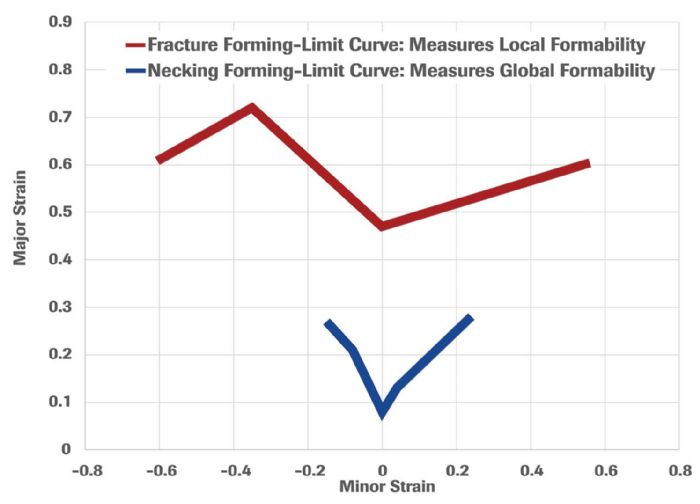 However, other failure modes occur during metal forming operations, primarily fractures that originate at either cut edges or at the outer surface of bends with tight radii. The ratio of bend radius to sheet thickness, along with the material strength and microstructure, controls the latter type of failure. The factors influencing edge fractures are far more complex.
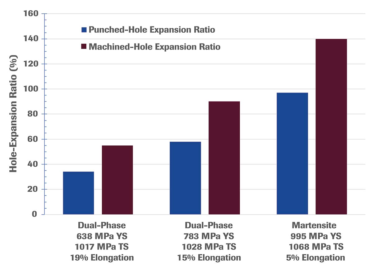 We must also examine the affected portion of the steel required for each type of failure. For necking failure to occur, strains through the entire sheet thickness must exceed the necking failure limit. This is not difficult when the failure locates in the body of a formed part, as tensile deformation occurs throughout. In contrast, consider a bend around a tight radius. The highest strains occur at the outer surface, with the strain levels decreasing at locations moving toward the inner surface. Strains exceed the necking failure limit only on the outer surface but not through the thickness, reducing the likelihood of necking failure at bend radii.