After researching various tool-steel options for the fender project, the firm settled on DC 53, an alloy manufactured in Japan by Daido Steel and marketed in the United States by International Mold Steel, Florence, KY.
“We also investigated several different tool coatings for the DC 53 tools, eventually specifying a proprietary coating after first testing the tools with coatings deposited by ion-nitride and titanium-nitride processing,” says Snyder. The firm also tested a variety of drawing lubricants, settling on a dry lube supplied by PPG. “Wet lubes failed to withstand the drawing severity and heat created during the draw,” adds Snyder. “We’ve deep-drawn stainless steel before—more symmetrically shaped parts such as wheel inserts for tractor-trailers. But the asymmetrical fenders are more challenging, creating forces that proved difficult to balance with conventional materials and lubes.”
The combination of DC 53 tool steel, the proprietary tool coating, and the dry lube proved very successful for drawing the stainless steel. The firm expects an increase in tool life by a factor of three to four compared to aluminum-bronze tooling, Snyder says.
Extreme Cushion Tonnage Required
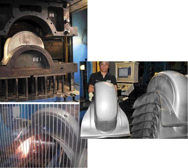
With tool steel and coating specified, the firm went to work developing the blank and draw-bead layout, to provide the required holding force to complete the 9-in. draw, yet minimize the size of the addendum.
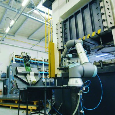
“We focused a lot of time and energy profiling the cushion tonnage and other press parameters,” adds Snyder, describing the process developed to draw the fenders on a 2002-vintage 850-ton AP&T hydraulic press. The press boasts a 450-ton cushion and 63 by 99-in. bolster.
“We have to use a relatively high cushion force of 300 tons,” Snyder says, “probably 2.5 times what we’d use for a mild-steel blank of this size. We also use a larger-than-typical blank in order to keep the shock lines off of the Class A surface. To minimize oil canning and manage the residual stresses building up in the sidewalls during drawing, we located the draw beads outside of the Class A surface, which necessitated a wider blank than we might typically use. This contains the stresses in the offal.”
Residual-Stress Buildup a Challenge for Laser Trimming
After a single draw in the press, parts move to one of four five-axis laser-cutting machines at Tools, Inc. All of its laser-cutting machines were provided by Prima North America, Chicopee, MA.
“Laser trimming of deep-drawn parts has really taken off for us,” shares Tools, Inc. sales manager Mark Voegeli, “not only for stainless-steel parts but for some of the newer advanced high-strength steels gaining in popularity. Some of these alloys are too hard to trim using traditional dies. We’ve added two laser-cutting machines in the last couple of years to better handle this type of work. Trimming the Rocker motorcycle fender would have taken multiple die hits, rather than one setup in the laser cell.”
Each of the firm’s laser-cutting machines are dual-cabin setups that allow cutting in one cabin and load/unload in the second cabin. Or, the partition separating the two cabins can be removed to allow processing of large stampings.
Laser-trimming the deep-drawn fenders proved challenging as the exceptionally high residual stresses in the sidewalls initially caused the stampings to shift in their fixtures during cutting. “The the scrap would peel off of the part during trimming caused us to re-engineer the laser-cutting fixture,” shares Snyder. “We had to develop a combination of electronic, mechanical and pneumatic clamps and use proximity sensors to gauge the part during fixturing, and to more securely hold the part during cutting. The sensors check the location of critical-tolerance part features to within ±0.010 in. The fender has subtle form features that must be accurately located relative to the trim line.”
On to Restrike
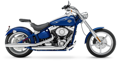
After laser trimming, the Rocker-motorcycle fenders move to a 1000-ton hydraulic press for punching (to make holes for the license plate and tail-light brackets) and then are hand-transferred to a second die for a restrike operation, to straighten the sidewalls.
“The success of this project, and other more challenging deep-draw work,” shares Snyder, “comes from our recent investments in new hydraulic-press technology, laser-cutting capacity, tool-steel development, and our ability to try out and develop dies virtually using the Dynaform software. We’re poised to perform the most complex draws that designers can draw up, particularly with the newer high-strength steels as well as stainless steels.” MF
View Glossary of Metalforming Terms
See also: ETA (Engineering Technology Associates, Inc.), International Mold Steel, Prima Electro North America, LLC
Technologies: Materials, Pressroom Automation, Tooling


