


 Anthony Rante
Getting the Most from Mechanical Presses
December 1, 2017Comments
Your understanding of press design and how it limits die loads could be life-changing…for your mechanical press. The following design parameters for single, transfer, or progressive-die applications must be addressed as you plan dies for your press.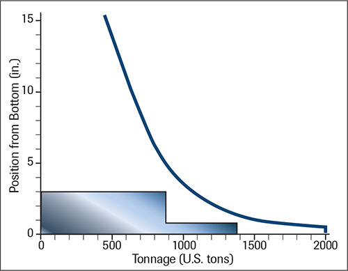
Fig. 1—Shown here is a typical mechanical-press tonnage curve, 2000 tons with a 0.5-in. rated position, with actual die loading shown. Note that peak tonnages remain under the curve. The area under the curve represents the required energy per stroke.
Tonnage Curve
Each mechanical press should include a tonnage curve within the documentation set. The curve, a plot of press position vs. tonnage, is important for die planning. The rated position of the press, typically about 0.5 in. from bottom, means that the full tonnage of the press can be applied in the dies between the rated position and the bottom of the stroke. The press designer will determine the main gear torque at the rated position, and then hold that value as a limitation at all points above the rated position. Since the press linkage loses mechanical advantage above the rated position, the resulting allowable tonnage decreases. The reduction in tonnage above this point is less significant for link-drive presses, as the mechanical advantage drops off at a less dramatic rate.
All dies must maintain loads within this curve. For example, starting a draw at 3 in. above bottom on a 2000-ton press likely will limit force to approximately 1000 tons. Although loading the press above this point will not overload the frame, or signal an overload at the connection, the drivetrain will experience excessive gear loads. This is true because the main gear torque, used to size the gears and shafts, represents the design limitation at this point. Fig. 1 illustrates a typical tonnage curve for a mechanical press.
Energy
A mechanical press is limited in available in.-tons of energy per stroke, with the flywheel supplying the energy for making the part. The main motor adds energy to the flywheel as energy depletes during part forming. Typically, the press designer allows for a 10- to 20-percent drivetrain slowdown during each stroke. This dictates the energy-per-stroke limitation for die loading. The allowable energy per stroke is supplied by the press designer and included in press specifications. During die planning, be aware of energy per stroke, and the speed at which this specification is presented. As the flywheel rotates faster, it generates more energy. However, if the press energy and speed relation aren’t understood—common during communication of press specifications between customers and OEM press manufacturers —the main motor may be undersized for energy production at that higher speed.
Determine the energy per stroke for a particular part using the same tonnage curve, as shown above in Fig. 1. For example: If we apply 1000 tons at 3 in. above bottom continuously through the bottom of the stroke, energy per stroke is 3000 in.-tons. Plotting this profile on the curve shows that the area under the curve equals the energy. If the force increases to 1500 tons within the last 0.25 in. of stroke, the energy required will increase. Using the same area-calculation approach, determine the total required energy by summing up all of the area under the curve.
Offset-Loading Considerations
The amount of offset loading applied in the dies represents another die-loading parameter to address. This typically becomes a bigger issue in transfer- or progressive-die applications. The die is more centrally located for single-die applications and tends to apply a balanced load in the press. But die loads can be higher at the entrance end than that at the exit end for transfer- and progressive-die applications. Since most press designs are based on uniform capacity across the area from left to right, die loading must be planned so that each half of the press is within 50 percent of the capacity.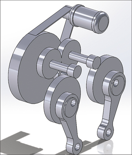
Fig. 2—Shown here is a typical mechanical-press drive train with a slider-crank (eccentric-drive) linkage. The flywheel produces the energy for part forming and is replenished with each stroke.
A good rule of thumb for offset loading from left to right: Limit the maximum deviation within a 60/40 percent criteria. This means that if 50-percent tonnage is applied on the entrance end of the press, but only 15 percent is applied at the exit end, the offset rule of thumb is violated. A common approach to solving this scenario is to add nitrogen die loading to help bring the offset back to a more uniform load. Running a mechanical press with a high offset tends to increase slide-gib wear and cause other bearing-wear issues.
Using a 2000-ton press as an example, the 60/40 percent rule can control the offset load. If the entrance side of the press runs at full tonnage of 1000 tons, then the right side should be loaded with at least 670 tons. This loading shows a total die load of 1670 tons, as the entrance side loads at 60 percent of this amount, and the exit end loads at 40 percent.
Take the Challenge
Maintaining limitations for die loading is worth the effort. Develop a log of die tonnage, corresponding-position in.-stroke, and energy per stroke. Tonnage-monitoring devices help to document tonnage and provide understanding of the corresponding-position in.-stroke.Always demand that the tonnage and energy specifications for new equipment be provided, and be sure that they are clearly documented and explained. Used equipment may require more investigation to obtain these critical specifications.
Bottom line: Taking the time to obtain press specifications and evaluate actual die loading matters. It’s a challenge worth taking. After all, the life of your mechanical press depends on it. MF
View Glossary of Metalforming Terms
See also: Artech Engineering Inc.
Technologies: Stamping Presses
Comments
Must be logged in to post a comment. Sign in or Create an Account
There are no comments posted. Stamping Presses
Aida Receives Recognition for its EV Drive-Motor Core High-S...
Monday, February 5, 2024
Executive Interview with Bruderer Americas President AJ Rupp
Friday, February 2, 2024
 Video
Video Stamping Presses
Bruderer to Build New UK Factory and Showroom
Thursday, October 12, 2023
 Stamping Presses
High-Speed Stamping Presses: Are They for You?
Rene Zwahlen Monday, September 25, 2023