


Mapping Value Streams
Kimball Office began by developing detailed maps of its parts-manufacturing processes, flows and timing on the shop floor. This single, large and integrated value-stream map details all of the specific manufacturing steps, part-travel distances and the amount of time parts spend at each step.
To generate such a map, start at the incoming raw materials area of the factory and work your to the final shipping point of the finished piece. The map must include drawings of all of the steps, distances and timings, done on a large sheet of paper. Skip nothing. Document on this map the complete travel agenda for a given part. Include the temporary storage of parts in bins, awaiting further processing.
The map should clearly define the total throughput for the manufacturing of each part. A good value-stream map also incorporates all of the
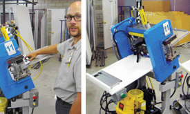 |
| Tooling is angled (left) to use gravity to help slide parts into position. Each set of tooling is sensored to cycle the part automatically once the part slides into the proper orientation. Once the tooling has cycled, the part automatically ejects into the exit tray (right). |
Explosion and Compression
After completing a highly detailed value-stream map, the metalformer then should mentally explode the entire process into its essential and discrete manufacturing elements; Kimball Office’s team analyzed each element within its place in the total picture. Free your mind to imagine piercing, forming, bending, staking, hardware insertion, welding, drilling, tapping, etc. into discrete and separate steps, and liberate those steps from the current dies, presses, tooling and machinery currently being used. This will allow you to restructure them with simpler tooling and machinery.
Tough questions must be asked, such as, “Could I combine this step on the value-stream map that occurs in the left side of the building with a completely different step that occurs several hundred feet a?” Or, “Could this hole being pierced on station six in a large progressive die be pierced in a smaller, simpler die that also might incorporate a bend currently being performed separately on a press brake 200 yards a?”
Hold back nothing. Ask all forms of creative questions during this process. You just might find that for a given part you do not really need a large and expensive 14-station progressive die and a 400-ton press, but rather a series of much simpler dies and machines. This is precisely what Kimball Office managed to do with one of its parts-manufacturing operations.
Chaku-Chaku
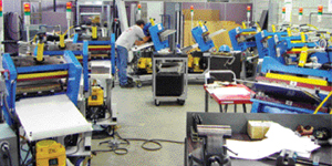
Roughly translated, the Japanese term “Chaku-Chaku” means “load-load,” but in the manufacturing environment it refers to a single-piece manufacturing process in which a worker takes a part from one workstation to the next—one worker, several tasks. He sets up and operates each machine from the beginning to the end of the production cycle. This concept is at the core of the Kimball Office philosophy of right-sized tooling and machinery, and guided the company as it replaced a complex and expensive set of processes that once occupied thousands of square feet of plant space with a greatly simplified room-sized series of right-sized stand-alone machines and tooling.
Kimball arranged the machines and tooling in its new line sequentially so that one person can operate the entire line. The operator walks from machine to machine placing the part into the tooling and then removing the previously processed part and placing it into the next adjacent machine. The right-sized equipment processes the newly inserted part unattended while automatically unloading the previously processed part. This frees the operator to perform other activities while the part is being processed.
As production runs, each piece of equipment has one piece of processed product in the output tray—the operator advances the part from machine to machine. The tooling is angled to use gravity to help slide parts into position. Each set of tooling is sensored to cycle the part automatically once the part slides into the proper orientation. A system of colored lights lets the operator know that each step in the process is working properly—the operator need not sit in front of a gap press, for example, and precisely align the part into the tooling. Once the tooling has cycled, the part automatically ejects into the exit tray.
Simple and Single Functioned
The equipment is designed to be simple and single functioned for reliability and to simplify construction.
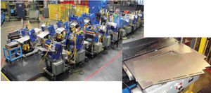 |
| This Chaku-Chaku production line completes drawer-front forming operations in 13 small presses configured in a U-shaped line. Each forming press performs one bend. The machines cycle unattended and unload automatically. Below: A drawer-front blank exits the blanking press. |
The machines are configured in a U-shaped production cell located close to the point of use, to minimize part travel and operator distance. The production line is extremely flexible to accommodate changes in production volumes, by simply adding or removing operators from the production cell. Only actual customer-required part orders are processed in the cell, made possible because there is little or no setup required. Equipment is dedicated and the line can produce the entire product mix without additional setups.
Further, tooling costs are significantly less than with traditional stamping dies, making the line profitable at lower production volumes. Equipment is mobile—on casters—so that when the product mix changes, the tooling and machines can be easily reconfigured. Therefore, the cost of the entire line of machines can be amortized over the lifetime of the various processes.
Apples to Apples
Ken Lambie, Kimball Office’s tooling manager and overseer of the firm’s right-sized manufacturing program, describes a typical job run on its new, right-sized Chaku-Chaku line.
“An excellent example of ‘Chaku-Chaku’ is use of the cell to manufacture a pedestal drawer,” Lambie says. The job comprises fabrication of two styles of drawer fronts—extended pull and attached pull—produced in two sizes, or four different parts.
Describing the process, Lambie says that, “Cold-rolled steel coil feeds through the back of a small press into a die, which profiles the bottom features of the drawer front and cuts the drawer-face blank to size. The press feed is programmed to feed to four different lengths. The operator presses one of four buttons to select the required drawer-front blank, then picks up the drawer blank from the output tray. The coil advances and the press cycles. One drawer blank sits on the output tray waiting for the operator to return. The operator then places the drawer blank—profiled on the bottom and cut to length —into one of two gravity-fed notch dies, which profile the top of the drawer blank. One press profiles the top of the extended-pull drawer front and the other profiles the top of the attached-pull drawer front. This strategy enables all four drawer fronts to be blanked without any setup changes.”
The production line completes drawer-front forming operations in 13 small presses configured in a U-shaped line. Each forming press performs one bend. The machines cycle unattended and unload automatically. The first five machines complete the bends on the top of the extended-pull style drawer front, and machines six through 11 complete the bends on the sides and bottom of all four drawer fronts. These features are common to all of the drawer fronts. Machines 12 and 13 form the top of the attached-pull drawer front.
“Creativity was required to develop a strategy that completely eliminates any setup required to eliminate batch production,” says Lambie. “The extended-pull drawer front requires two resistance-spot welds to complete the formed drawer pull. We modified a standard rocker-arm welder with simple automation to allow welding with the machine untended by the operator.”
One-hundred-percent of the drawer fronts are inspected in an automatic check fixture that measures every drawer front with analog proximity sensors. The check fixture (which uses LabView software from National Instruments, Austin, TX) displays each measured value and indicates pass or fail. Also, as a measurement nears the tolerance limit, values display in yellow to indicate when parts drift toward the tolerance limits, so that action can be taken prior to producing a bad part.
Dramatic Results
Kimball Office implemented the production line in October 2006 and has documented the following improvements:
| Measure | Before | After |
| Inventory | 7700 pieces | 400 pieces |
| Crew size | Four | Two |
| Setup time | 60 min. | 0 |
Lead time | 3.8 days | 10 min. |
| Product travel | 720 ft. | 32 ft. |
Management Support
The unwavering support from upper management for right-sized machines and tooling has proved crucial to the success of the above-described project, and others, at Kimball Office. Don Meyers, plant manager, not only has provided his complete backing for the projects but also has implemented a plant-wide program for employee training that blends the best practices of lean manufacturing with right-sized technologies.
Over the last four years, Kimball Office’s right-sizing manufacturing technology team has developed and implemented production lines using more than 70 pieces of right-sized tooling and machines. Advancements continue to be made in equipment design to improve reliability, quality and cost reduction.
On September 25, Kimball Office will host a seminar detailing the technologies described in this article, followed by a tour of its facilities. For more information, go to www.mfgadvice.com. MF
View Glossary of Metalforming Terms
Technologies: Stamping Presses, Tooling
Comments
Must be logged in to post a comment. Sign in or Create an Account
There are no comments posted. Stamping Presses
Aida Receives Recognition for its EV Drive-Motor Core High-S...
Monday, February 5, 2024
Executive Interview with Bruderer Americas President AJ Rupp
Friday, February 2, 2024
 Video
Video Stamping Presses
Bruderer to Build New UK Factory and Showroom
Thursday, October 12, 2023
 Stamping Presses
High-Speed Stamping Presses: Are They for You?
Rene Zwahlen Monday, September 25, 2023