Increasing Output with Servo
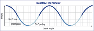
The ability, with a servo-mechanical drive, to synchronize slide speed with process conditions over the entire press cycle allows stampers to increase output. Consider the four segments of the forming stroke: die, die opening, transfer/feed and die closing (Fig 2).
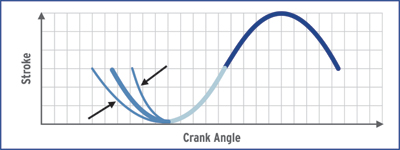 |
| Fig. 3—The die-process stroke segment—timing is influenced by in-die operations. |
During the die segment of a stroke, the goal is to adapt to the best possible forming speed for a particular part while considering in-die functions such as spring and cam actuation. Optimizing forming speed allows stampers to improve process reliability and part quality (Fig. 3).
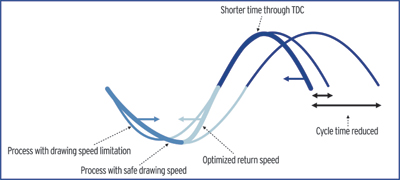
During the die-opening segment of the stroke, the goal is to create accessibility as quickly as possible to avoid losing time in the full press cycle. However, in-die functions such as spring and cam actuation might limit maximum opening speed. The ability to manage opening speed within the cycle contributes significantly to overall process efficiency (Fig. 4).
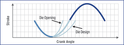 |
| Fig. 4—The die-opening stroke segment—quicken this portion of the stroke and overall cycle time improves dramatically. |
During the part-transfer segment of a stroke, the stamper hopes to synchronize slide movement with the motion of transfer automation. Movement and time required varies with the transfer device (Fig. 5). This is especially significant when considering the use of a two- or three-axis transfer system, three-axis transfer in crossbar mode or with turnover capability, which would require more time.
With each segment of the overall cycle optimized, the net result can be significant, with better conditions for forming high-quality parts while reducing the time for die opening and die closing. Depending on the requirements of the application, this can result in reduced cycle times and higher production rates (Fig. 6).
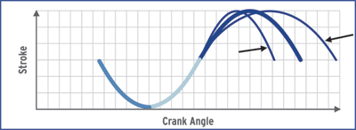 |
| Fig. 5—Adapting slide characteristics to transfer timing. |
In general, the relative increase in output when using a servo press peaks when applied to systems running a variety of parts. Servo drives offer flexibility to vary the slide characteristic for different parts and transfer requirements.
For progressive-die applications, output can be further increased by reducing the slide stroke while using a pendulum movement—the gear rotates between 90 and 270 deg. in the drive, rather than full 360-deg. rotation—using only half of the full stroke length. The time saved by not completing the full stroke results in increased output rates (Fig. 7). Pendulum movement is possible with any type of servo-press design; however, on less dynamic servo-press systems, the time needed to stop and restart at half-stroke actually could result in longer cycle times.
 |
| Fig. 6—Reduced cycle time, while improving the forming process and part quality. |
Example: Progressive-Die Airbag-Cartridge Holder
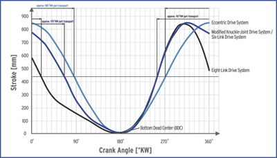
Consider the stamping of an airbag cartridge-holding part. A traditional eccentric-drive press might stamp the part at 25 strokes/min., with a 2.4-sec. cycle speed limited by the forming process (Fig. 8).
Producing the same part on a servo-mechanical press, the stamper can reduce slide speed before hitting the blank, and also use a slower drawing process to ensure optimum part quality and minimize part failures. In addition, after reaching BDC in the cycle, the stamper can program the press to gain speed more quickly than with a conventional-drive press, to regain the time lost due to the slower forming process.
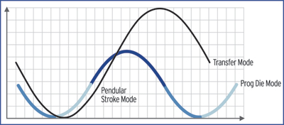 |
| Fig. 7—A pendulum stroke mode increases output rate. |
During complete opening of the die, the high rate of speed is maintained, stopping at TDC and reaccelerating after receiving a signal from the part feed that it is ready to repeat the process for the next cycle. The slide then travels down, again very quickly, but decelerates as the part is hit.
When measuring from TDC to TDC, the traditional eccentric-drive system operated at 25 strokes/min. Measuring the same for the servo-mechanical press cycle, the press would run at 40 strokes/ min., a 60 percent gain in productivity.
Drive Comparison
Fig. 9 compares the performance of a 315-ton conventional eccentric-drive press and a 400-ton servo-mechanical press, used to stamp a variety of automotive structural components. By optimizing the stroke cycle, the servo-mechanical-drive press yielded productivity improvements as great as 35 strokes/min.
Motor Improvements
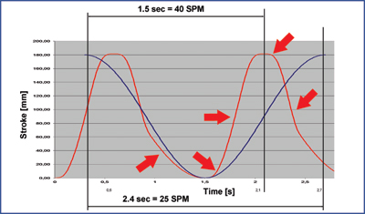 |
| Fig. 8—Stamping airbag cartridges on a conventional eccentric-drive press (blue) and servo-mechanical press (red) shows a 60-percent gain in stroke rate with servo. |
The past 20 years have seen numerous patents and designs developed to drive mechanical presses—screw, link, knuckle, eccentric—with a motor and without a flywheel or a clutch and brake. Driving these developments is the desire to simplify components and to improve the dynamic response of the press-drive system.
Simple electric motors have been available in large sizes for many years; the newest development is the drive controlling the motor. Recent improvements allow motors to operate at 0 to 3000 rpm to drive screw or eccentric links directly, without a flywheel and a clutch and brake. Even more recently, torque motors with operating capabilities of 0 to 400 rpm have been developed with improved electronic control and increased dynamic capabilities.
In a servo-mechanical drive, a servo or torque motor connects directly to the drive train. Output energy transfers into the drive train, with excess energy available to accelerate or decelerate the slide, or to develop press force. With a torque motor operating at a maximum of 400 rpm, only 40 percent of the torque is required to accelerate the drive train, leaving 60 percent to accelerate or decelerate the slide or to develop press force. However, with a servo motor operating at a maximum of 3000 rpm, 70 percent of the torque is required to accelerate the drive train, leaving only 30 percent for dynamic press operation.
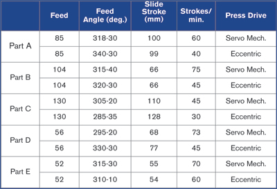 |
| Fig. 9—Various dies compared on eccentric and servo-mechanical die press systems. |
In short, the torque-motor drive system allows for a more dynamic system with greater potential to optimize the forming process and stroke cycle.
In a servo-mechanical drive design, the main motor is bigger than that in a conventional mechanical press, as it replaces the function of the flywheel and must provide total energy throughout the complete press cycle. The rest of the drive-train components are engineered the same manner as for a conventional mechanical press, using a geared drive train to convert motor rpm to press-slide motion. While the servo motor can accelerate and decelerate the drive train during all normal operations, a conventional brake is still needed to support the motor for slowing the slide in emergency situations.
Control Design and Functionality
The controls for a servo-mechanical share many of the same components used to control a conventional drive. The press PLC that controls functions such as lubrication and die change, PC visualization, press safety, control relays, smaller drives for slide adjustments and network electronics (routers for integration of press control to facility network and modem for remote access) all are the same. The biggest difference: the large drive and drive control for each servo motor, instead of one smaller drive for a conventional motor.
Servo and conventional press controls employ the same screen systems for press maintenance, diagnostics and die-change modes. The display for a servo-drive control adds a screen to show and allow modification of the slide motion curve. An operator can select among various preprogrammed motion curves depending on the complexity of the control, and can select a pre-implemented motion curve or, using an additional tool, modify and customize the motion curve.
A user has three s to modify the motion curve from the control screen. First, the motion curve can be adjusted much like with a hydraulic press, with modifications typically entered based on distance above BDC. Or, as with mechanical-press operation, modifications can be made based upon the crank angle of the main shaft. Thirdly, considering the die opening from the perspective of manufacturing tools and dies, adjustments can be made based on die closing and automation start and stop.
Energy Consumption
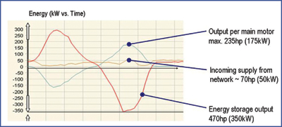 |
| Fig. 10—Main motor output supplied almost entirely by energy storage. |
A servo press, like a hydraulic press, has a direct drive. The large motors used to operate large servo-mechanical presses require a significant amount of electricity to generate full tonnage. Conversely, a conventional mechanical press obtains the energy needed throughout a complete cycle from the flywheel.
Looking at a typical press cycle, the press consumes higher amounts of energy during drawing, cutting and forming, and when accelerating the slide. On the other hand, the press generates energy whenever the slide is slowed. In a conventional mechanical press, the energy generated during deceleration automatically stores in the flywheel; in a hydraulic press, this energy is lost; and in a servo-mechanical press it can be stored or, in some cases, fed back to the facility network, depending on the connected load of the press with regard to the maximum load of the motors. Rather than feeding to the network, it can route to an energy-storage device within the servo press. Storing the energy within the press allows the stamper to reduce the size of the main line connection by as much as 30 to 70 percent.
The example in Fig. 10 illustrates power storage and output in a servo-mechanical press system over the course of a cycle. Operating with two main motors, each with a maximum output of 235 hp, the excess energy stores in an energy-storage device during deceleration and then is drawn upon when the press requires more than 235 hp. Because the stored energy (max of 470 hp based upon output of two motors) is used during peak power requirements, the load on the facility network remains fairly constant at approximately 70 hp.
Two available methods to save the energy generated by deceleration of the slide are capacitor storage or by a motor/ generator connected to a rotating mass. The more reliable and longer-lasting method is a motor/generator, but ongoing developments in capacitor capabilities will likely make capacitors the preferred storage option of the future.
Part Design and In-Die Operations
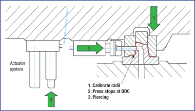 |
| Fig. 11—Piercing integrated into a forming operation. |
The ability to incorporate in-die operations can significantly reduce overall part-processing time and cost, and potentially allow more complex part designs. For some in-die operations (Fig. 11), the press slide must stop at a certain position to carry out the operation. This action becomes more feasible with the use of servo-drive presses, and often may not even be possible with a conventional flywheel press. The more dynamic the system behaves, the less time lost during stopping and restarting.
The dynamics of the servo-drive also can influence die design. For example, because of the ability to slow the slide before contact, the need for a spring-loaded subplate might be eliminated. Or, perhaps a less expensive die material can be used for a low-volume application, since a more controlled slide motion can minimize wear.
Also, when performing secondary operations in the die, the need for expensive cams might be reduced or even replaced by hydraulic/pneumatic/ servo actuators that do not have to be synchronized, since the slide motion can be infinitely controlled. With the ability to control the height of the die opening, the length of the guiding columns and overall die height can be reduced, as well as the spindles activating tap drills. MF
Industry-Related Terms: Modem,
Point,
Run,
Stroke,
Torque,
Transfer,
Cam,
Blank,
Die,
Center,
Hydraulic Press,
Drawing,
FormingView Glossary of Metalforming Terms
See also: Schuler North America
Technologies: Stamping Presses


 Video
Video