Response: The estimated-force calculation in the book assumes a worst-case scenario because it relies on ultimate tensile strength (UTS) in the formula. The deformation process (drawing) begins when the material reaches its yield stress, which can be significantly less than the UTS, and as the material work-hardens it increases in strength. Theoretically, the material could be worked up to its UTS, which is why it is used in the formula. But not all deep-draw parts reach this level of work hardening, so the actual drawing force could be considerably less.
The book formula also assumes that the maximum draw reduction is being taken. When the draw reduction ratio approaches 1.8:1, we have the near-maximum blank area in contact with the blankholder, which means that more friction must be overcome and a greater area of material must be deformed (the flange of the blank deforms by thickening). Smaller draw-reduction ratios certainly would require less force to deform the blank, but I am not aware of any coefficient to apply to the force calculations that would account for this. Personally, I would not use the coefficient from the online calculator without a better understanding of its purpose and how it was derived.
Regardless of which formula used, this job falls outside of the capacity of your press. One reason is that you must also add in the force of the blankholder, which typically amounts to approximately 30 percent of the drawing force. Because you are drawing relatively thick material, the required blankholder force could be as low as 20 percent. That puts you at around 451 tons using the online formula, and assumes that nothing in the die will hit home or bottom out, or that the blankholder pressure will not have to increase.
Secondly, if this is a mechanical press and not a hydraulic press, you will not have enough tonnage or press energy to carry out the deep-drawing process, even if the calculated tonnage falls below the rated press capacity.
Mechanical-press capacity is rated slightly above bottom dead center (BDC). In the accompanying tonnage graph, the 600-ton rating for this press occurs at approximately 1⁄2-in. above BDC. Deep drawing requires working the material high in the press stroke where derated tonnage comes into play. In this example, a 600-ton press has approximately 280 tons available at 2 in. above BDC.
Drawing Aluminum
Question: We have a job that uses 0.05-in.-thick 1100-0 aluminum. We use a 12.5-in.-dia. blank to draw a 4-in.-tall, 8-in.-dia. dome with a 1.5-in. flange (trimmed later). This is performed in a single draw.
This job has been running for nearly 60 years. We had been successfully drawing this part using a lubricant that is no longer available. We substituted with another product that tended to separate and not perform as well. We experimented with other lubricants but had minimal success.
This die uses an air-cushion blank-holder to hold the flange during forming. We can reduce the pressure and make some parts that do not crack, but the flange is too wrinkled to use.
Response: A follow-up conversation with the reader revealed that some testing was conducted using thin, plastic food wrap and a very thick oil additive, with little success. The plastic wrap would shred and tear and became difficult to remove after forming.
The stamper decided to use a lightly oiled trash bag, as it is thicker and can stretch farther without tearing. The trash bag also serves as an ideal lubricant for troubleshooting because it provides a very low friction coefficient. If the part can be produced with the oiled trash bag, then we know that the material can make the part and that lubrication is the problem. If the part fails when using the oiled trash bag, then the material must be addressed because no better lubrication option exists.
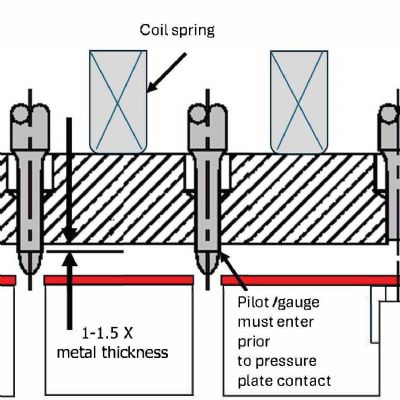
Because making a good part also was sensitive to blankholder pressure, I suggested measuring the thickness of the blank material and making some shims that measure approximately 0.005-in. greater than the material thickness. The shims are to be placed on the blankholder, outside of the blank periphery. The blankholder pressure now can be increased to suppress the wrinkles without placing excessive pressure on the blank and causing the part to fracture. If wrinkling continues to occur, the shims can be ground down in 0.001-in. increments until just enough restriction is provided to suppress the wrinkles but still allow free material flow into the die cavity.
Facing a problem in your shop? Be sure to approach it as a system of inputs and outputs, not simply as a die issue. Too often we try to solve material, lubrication and machine-related problems as die issues. Sometimes these problems can be compensated for in the die but doing so only prevents us from finding the root cause. MF
Industry-Related Terms: Blank,
Center,
Die,
Draw,
Drawing,
Flange,
Forming,
Hydraulic Press,
Periphery,
Stroke,
Tensile Strength,
Thickness,
Work Hardening,
WrinklingView Glossary of Metalforming Terms Technologies: Tooling


 Peter Ulintz
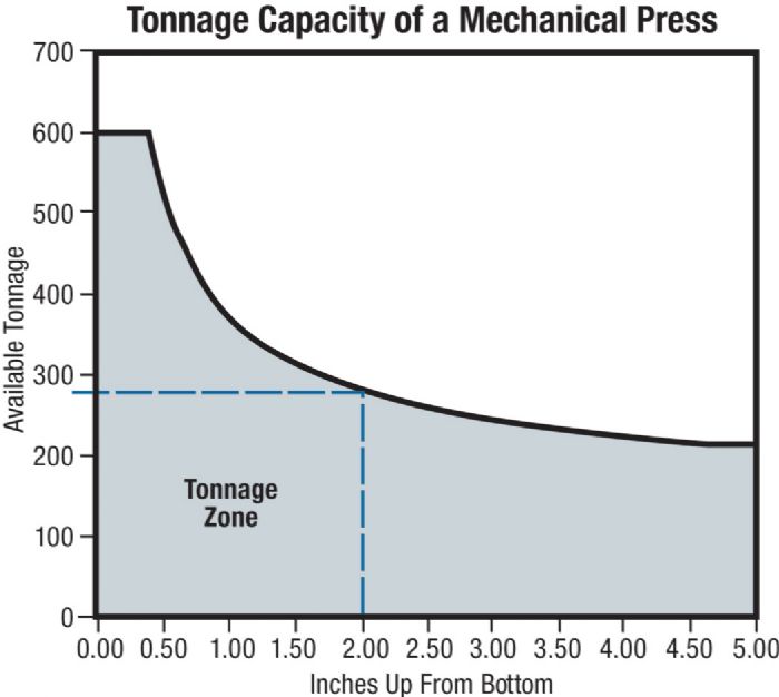 Question: We are trying to calculate the tonnage on a job that we are quoting. Our estimator has been quoting jobs for a great many years and has relied on calculations derived from the book “Condensed Practical Aids for the Experienced Die Engineer, Die Designer and Die Maker.” The book offers this formula: