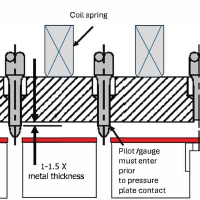
A pitch notch or pitch stop can provide a physical point from which to locate and control the leading edge of the strip. Stampers can mount the pitch stop on a pivot and monitor it with a sensor to prevent the press from operating with either a short or long feed. In some cases, the stamper can replace a pitch notch with an edge-form or lance-form operation. Here, the bent material stiffens the carrier to allow for smoother feeding (Fig. 2). If desired, the bent edge can be encapsulated in a modified guide rail to prevent edge bending or buckling in dies with long pitch lengths.
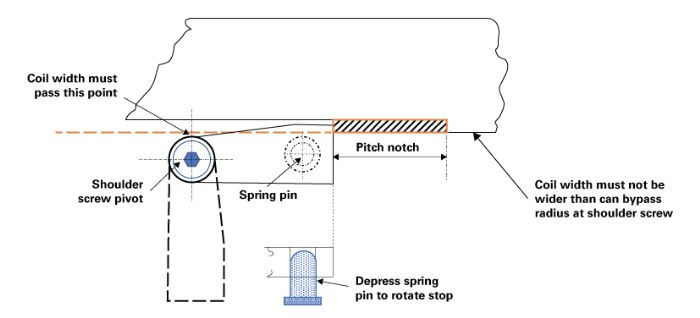
 Coil changes require removing the remaining strip from the die by pulling it through the exit end of the die, or by backing it out of the entry side. The combination of formed features and a pitch notch in the strip may prevent strip removal. In these cases, the operator will need to cut the strip into two pieces and remove them from opposite sides of the die, which can be time-consuming and usually requires hands to be within (or close to) the point of operation. In some cases, a rotating pitch stop (Fig. 3) can facilitate removal of the strip in one piece through the exit side of the die without the need to cut the strip.
Part Lifters and Part Feeding
 Progressive dies often require the strip to be lifted from the die working level to the feed level before the strip can feed forward. Even flat pieces must be lifted slightly to break the oil seal with the die. The amount of lift can vary from a small amount—to clear trim and punching burrs—to several inches to allow deep part shapes to clear the die. In general, take care to design the die with minimal lift height—the higher the lift the greater the impact on feeding the strip due to vibration or bounce.
If all of the forms are in the same direction, the parts can be formed in the up direction to reduce lift—but usually at higher die cost. Design the lifters to lift and support the entire strip to an equal height and level plane to the feed unit. The lift system must ensure that the strip does not sag between lifters; otherwise, parts will be pulled out of their correct location.
Bar lifters usually provide better support than spring pins or round lifters notched on one side. A good bar-lifter system permits higher press speeds because it will eliminate feed problems associated with round lifters and lift pins. Although the initial cost is higher, bar lifters will improve performance, reduce setup time, and avoid the need for the operator to place his hands (or tools) inside of the die to thread the leading edge of the coil over pins or through notches in round lifters. Full-length bar lifters also reduce the chance of formed edges, trim edges and holes from catching on the lifter system.
Edge camber in the coil can cause the strip to bind in the stock guides during the feed cycle. This binding may cause the carriers to buckle, resulting in short feeds. It often helps to relieve the stock guide in-between stations and have tighter control only at the working stations. Another option to eliminate camber: Trim both sides of the material in the beginning of the die.
If the action of the die as the press opens and closes requires the carriers to flex, design the carrier with loops long enough to flex without breaking but still strong enough to feed all of the parts to their full progression. If two carriers are not strong enough to feed the strip, consider using three.
Other factors affecting progressive-die performance include setup accuracy, feed alignment, feed speed and pilot-release settings. Coil shape exiting the straightener not only affects the ability to feed the strip but also can play a major role in part quality. We’ll discuss these factors next month. MF
Technologies: Tooling


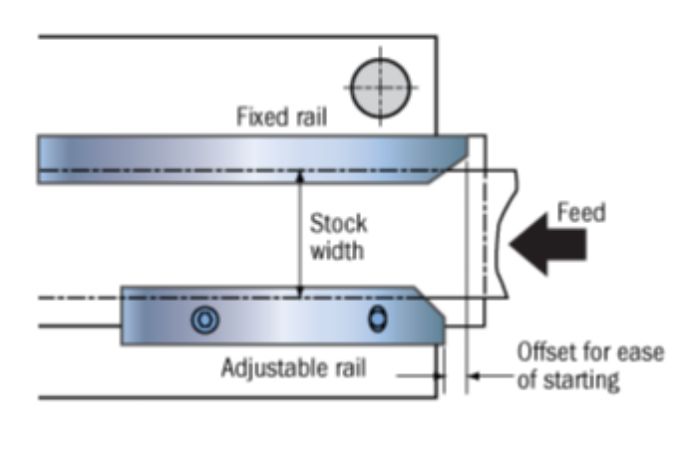 …requires care to ensure that the strip feeds correctly into the die. Large leads on the entry side of the die, along with offset rails, can ease starting and positioning of the lead edge of the strip (Fig. 1). Improper location of the leading edge can result in an unbalanced forming or flanging condition that can shift the upper die in relation to the lower die. It also may lead to small pieces of scrap being left in the die due to a partial hit. Metal tags or marked grooves can provide a visual location, but these are not as accurate or effective as a pitch notch or pitch stop.