Robert Cohen Robert Cohen
CEO

Addressing Limiting Factors for Continuous Seam Welding—Part Two

March 1, 2019
0
Comments


Machine capability and control capability determine how fast a production seam welding process operates. Speed increases until a limit is reached for four machine parameters: wheel velocity; current required for producing welds; cooling to keep electrodes and current-carrying conductors from getting too hot; and electrode force required to maintain material containment during the formation of each weld.


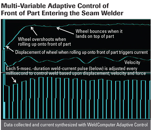
Front end of part: Adaptive seam welding at 22.5 in./sec.

Selecting a control with a high-enough operating-current limit, such that current is not the limiting factor in determining how fast welding can occur, ensures that the adaptive control runs the machine at maximum speed while maintaining weld-consistency standards.

This article digs deeper into what fabricators must know about machine parameters and controls for ensuring consistent continuous seam welds.

Velocity and Electrode-Force Variations

As the speed of a seam welder increases, variable loading of the part presented to the machine, motor-torque limitation, gear backlash, belt oscillation, less-than-optimum tuning of the motor-control-feedback parameters and machine mechanical resonances can cause significant instantaneous wheel-velocity fluctuations. Increasing the speed also reduces the time available to make each weld. As the weld time decreases, instantaneous velocity fluctuations increase weld variation. Velocity variations on a seam welder translate into variations in the size of the welds produced. Reducing velocity fluctuations from an existing machine could require impractical and costly engineering design changes.

Another challenge: As the speed of a seam welder increases, so does electrode-force variation, a source of weld variation. As the seam wheels roll up onto the front of the part at high speeds, the wheels often overshoot and bounce onto the part. The momentary higher electrode force caused by the bounce can translate into an undersized weld, causing a leak. Depending on the resonant characteristics of the electrode-force system, the step of the wheels rolling up onto the part can excite a machine resonance, which could take several oscillation cycles to subside. Each of these oscillation cycles can translate into a weld that is too cold as the wheel bounces down on the part, followed by a weld that is too hot as the wheel bounces off of the part.

Just as with reducing velocity fluctuations, eliminating electrode-force fluctuations caused from exciting resonances on an existing machine could require engineering design changes and retrofits that would be impractical and cost-prohibitive to perform.

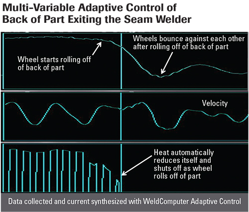
Back end of part: Adaptive seam welding at 22.5 in./sec.
The solutions for both these challenges: an adaptive control that can be installed on any seam welding machine. For weld-velocity fluctuations, an adaptive control can adjust the heat up and down in response to instantaneous wheel-velocity fluctuations, resulting in fewer weld variations. The same is true for electrode-force fluctuations; the adaptive control automatically adjusts the heat up and down in response to force fluctuations.

Current Concerns

Increased wheel speed requires higher current and faster welds because the spot must be produced and completed before a substantial portion of the wheel surface rolls away from the site of the weld. Accurate delivery of short-duration, high-current impulses are required to control weld repeatability. Cool time between each of these weld impulses aids the formation of individual overlapping weld nuggets, and reduces the operating temperature of the seam welding wheels. Reducing the temperature of the seam welding wheels generally improves weld quality, extends the life of the electrodes and reduces machine-maintenance requirements.

SCR Controls

In many seam welding operations, the control limits the speed at which a machine operates. As the manufacturer attempts to increase production-line speed, the control often becomes the biggest source of variability in the welding operation, causing high scrap rates, high losses due to reduction in overall production throughput, losses from destructive testing, and labor losses connected to many attempts to identify and keep problem parts from leaving the factory.

Existing seam welding operations using older technology—silicon-controlled rectifier (SCR)-based weld technology controls to drive a single-phase AC welding transformer—are limited by the control technology used. This limitation is coupled to the frequency of the power delivered by the power company, with the number of welds per second produced by the seam welder being equal to the number of power half-cycles per second delivered by the power company. On 60 Hz AC power lines, this means that the seam welding operation is limited to 120 weld impulses/sec., and on 50 Hz AC power this reduces to 100 weld impulses/ sec. The time of occurrence of each weld must be synchronized with the time that the power company delivers the half-cycle, not with the time desired to have the weld take place. As seam-wheel velocity increases, the requirement of having to synchronize the weld with the time of delivery of the half-cycle, instead of with the time that the part enters the machine, becomes a bigger source of weld variability that affects weld consistency on the edges of the part.

T. J. Snow Announces Regional Resistance Welding Seminar Dates

T. J. Snow Co. has announced the launch of its one-day seminar on resistance welding and its process variables. Beginning this month, seminars will be held at the locations below. The company also offers customized in-plant training and consulting. Registration information available.


The ability to regulate the heat of any individual weld impulse with an SCR control also is limited, because once the control initiates a weld half-cycle impulse, it has no further influence over what happens during the weld. The actual weld heat delivered depends on what the power company delivers during the half-cycle interval. The weld also is affected by the transient loading of other machinery in the factory.

Another limitation of SCR control technology: Once a weld impulse is initiated, it cannot be turned off by the control. In instances when the control triggers a weld impulse just as the wheels fall off of the back edge of the part, excessive sparking and material expulsion occur because it is not possible to terminate the heat.

Inverter Controls

In order to overcome limitations imposed by SCR control technology, some manufacturers performing high-speed seam welding switch to inverter technology with expectations for superior weld current regulation, improved weld quality and increased production throughput.

Manufacturers seeking expert advice often are informed that in order to take advantage of the newer inverter technology, it will be necessary to throw away the existing AC welding transformer and replace it with a newer technology mid-frequency DC welding transformer.

Wrong.

Several seam welding manufacturers that converted from single-phase AC to MFDC report decreased production throughput, reduced weld quality and increased maintenance. These problems worsened when the manufacturers programmed a shorter weld-impulse time and shorter cool time between each impulse in an attempt to try to meet or exceed the 120 welds/sec. impulse rate realized with the older technology control.

Examination of these welding operations reveals two fundamental causes for degraded welding performance:

  • The inverter control selected, when programmed to produce short-duration impulses, delivers inaccurate and/or unstable current regulation that results in greater weld-impulse current variability than what was previously achieved with the older SCR-based control.
  • During the programmed cool time between each impulse, the current decays slowly, and often doesn’t decay to zero before the next welding impulse begins. This high residual current during each cool interval, caused by the introduction of the MFDC transformer, degrades the effectiveness of the cool-time function. This causes the seam wheels to operate at a higher temperature to make the same sized welds than what occurred previously when the current could be brought to zero during the majority of the programmed cool interval. The elevated wheel temperature, caused from switching to an MFDC transformer, creates a number of secondary problems, which include: faster material pickup on the wheel surfaces, faster degradation of the wheel geometry, increased heat affected zone on the surface of the part and increased machine-maintenance requirements.

Other problems experienced with MFDC include:

  • Increased mechanical wear on the machine;
  • Magnetized machine and product, causing machine failures; and
  • Unbalanced temperature and wear of the two electrodes, resulting in weld variations.

Conclusions

We covered much in this article, but three takeaways are especially important:

  1. Employing a control capable of ensuring that every produced current impulse stabilizes at the programmed setting before programming a new value is necessary to maintaining a repeatable process accurately regulated by the control.
  2. The speed that a seam can be produced, while maintaining control of the process, can be maximized by employing multivariable adaptive control that can dynamically compensate for variations in electrode contact area on the part, electrode force, position and velocity as the seam is produced.
  3. Analyses of several high-speed seam welding operations have revealed that proper application of inverter technology to the existing AC welding transformer produces superior results to those achieved by replacing it with an MFDC transformer. MF
Industry-Related Terms: Edge, Electrodes, Lines, Scrap, Surface
View Glossary of Metalforming Terms


See also: Weldcomputer Corp.

Technologies: Welding and Joining

Comments

Must be logged in to post a comment.
There are no comments posted.

Subscribe to the Newsletter

Start receiving newsletters.