
Page 23 - MetalForming August 2010
P. 23
proper rigging also benefits from having employees understand the forces involved in moving loads. Motion, grav- ity and the strength of materials all affect how safely and smoothly a load can be moved.
Calculating Loads
To select the right rigging equip- ment for the job, employees must know the total load of the object being moved. The weight of a coil, for example, typi- cally is provided by the supplier, but if not, there are tables available that pro- vide the weight per cubic foot for stan- dard materials.
Shop personnel also must locate the load’s center of gravity. For regularly shaped objects, the center of gravity typically is located at the center of the object. However, for irregularly shaped objects like large stamping dies, you may have to make several adjustments before the load is balanced. Any load that tilts more than 5 percent after being lifted off the ground is unbalanced and must be readjusted.
Equipment Inspection
Wire rope finds use for jobs that require extra strength and abrasion resist- ance. Be sure to measure the rope peri- odically to ensure its diameter falls with- in acceptable parameters. Over time, stress on the rope wears away individual wires and elongates the strands. Once the rope falls below the minimum diam- eter recommended by the manufacturer, it is no longer safe for use.
Measure wire rope from the top of one strand to the top of the strand directly opposite it, rather than across two strands side by side. Rope manu- facturers also recommend measuring the rope at three places, at least 5 ft. apart, and using the average of the three measurements.
Rope also can become damaged from repeated dragging over surfaces. A com- mon cause of rope damage is repeated passing of the rope over a drum or through a block. Generally, abrasion resistance depends on the type and hardness of the metal alloy used to con- struct the rope and the size of the indi-
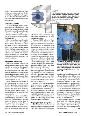
Over time, stress on wire rope wears away indi- vidual wires and elongates the strands. Meas- ure wire rope from the top of one strand to the top of the strand directly opposite it, rather than across two strands side by side.
www.metalformingmagazine.com
METALFORMING / AUGUST 2010 21
vidual outer wires—ropes with larger wires better resist wear than do ropes having smaller wires.
Chains are highly resistant to abra- sion and corrosion and find use for applications that would otherwise tend to damage fiber or wire rope. Still, chains must be inspected link-by-link prior to any rigging job. Begin by clean- ing the chain with a non-acid, non- caustic solvent so that marks, nicks and other defects become visible. Then lay out the chain on a flat, well-lit surface and examine links for stretching, bend- ing, cracks, wear and rust. Links often become bent or gouged when a chain has been wrapped around an object with sharp edges. Discard any chain that is bent at the weld point.
In a chain link, wear typically occurs at the bearing point. If you find a worn link, measure the cross section of the link with a caliper and check its meas- urement against an unworn area of the link. If the worn link is less than the minimum allowable thickness, remove the chain from service.
When inspecting chain slings, use the same criteria used to inspect a single chain. In addition, check the sling for proper identification information. The sling should have a tag or other identifi- er that gives the sling’s size, reach, work- ing-load limit, sling type, and a serial number with the manufacturer’s name or symbol. Do not use slings missing any of this identification information.
Angling for Safe Sling Use
Metalformers must keep an eye on sling angle when using slings to lift loads. Vertical and horizontal forces
Chains must be inspected link-by-link prior to any rigging job. Wear typically occurs at the bearing point. If you find a worn link, measure the cross section of the link with a caliper and check its measurement against an unworn area of the link.
come into play when lifting objects with a sling, and the amount of force exert- ed on the sling increases as sling angle decreases. A good rule of thumb: avoid sling angles less than 45 deg. Other- wise, consult with the sling manufac- turer on recommended sling angles, inspection criteria and proper use.
The capacity of the sling changes depending on the configuration—chok- er vs. basket, the number of legs on the sling and the angle of the legs. Basket hitches have higher working-load lim- its than do choker hitches.
When using a choker hitch, the ideal choke angle is 135 deg.; less than 120 deg. requires a reduction in the load. Never tighten a choker hitch during a lift; instead, pull the choker tight before the load is lifted. MF
