
Page 30 - MetalForming August 2010
P. 30
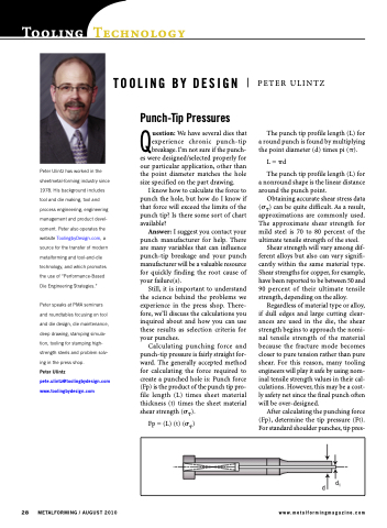
Tooling Technology TOOLING BY DESIGN
PETER ULINTZ
The punch tip profile length (L) for a round punch is found by multiplying the point diameter (d) times pi ().
L = d
The punch tip profile length (L) for a nonround shape is the linear distance around the punch point.
Obtaining accurate shear stress data () can be quite difficult. As a result, approximations are commonly used. The approximate shear strength for mild steel is 70 to 80 percent of the ultimate tensile strength of the steel.
Shear strength will vary among dif- ferent alloys but also can vary signifi- cantly within the same material type. Shear strengths for copper, for example, have been reported to be between 50 and 90 percent of their ultimate tensile strength, depending on the alloy.
Regardless of material type or alloy, if dull edges and large cutting clear- ances are used in the die, the shear strength begins to approach the nomi- nal tensile strength of the material because the fracture mode becomes closer to pure tension rather than pure shear. For this reason, many tooling engineers will play it safe by using nom- inal tensile strength values in their cal- culations. However, this may be a cost- ly safety net since the final punch often will be over-designed.
After calculating the punching force (Fp), determine the tip pressure (Ft). For standard shoulder punches, tip pres-
Peter Ulintz has worked in the sheetmetal-forming industry since 1978. His background includes tool and die making, tool and process engineering, engineering management and product devel- opment. Peter also operates the website ToolingbyDesign.com, a source for the transfer of modern metalforming and tool-and-die technology, and which promotes the use of “Performance-Based Die Engineering Strategies.”
Peter speaks at PMA seminars and roundtables focusing on tool and die design, die maintenance, deep drawing, stamping simula- tion, tooling for stamping high- strength steels and problem solv- ing in the press shop.
Peter Ulintz pete.ulintz@toolingbydesign.com www.toolingbydesign.com
Punch-Tip Pressures
Question: We have several dies that experience chronic punch-tip breakage. I’m not sure if the punch- es were designed/selected properly for our particular application, other than the point diameter matches the hole size specified on the part drawing.
I know how to calculate the force to punch the hole, but how do I know if that force will exceed the limits of the punch tip? Is there some sort of chart available?
Answer: I suggest you contact your punch manufacturer for help. There are many variables that can influence punch-tip breakage and your punch manufacturer will be a valuable resource for quickly finding the root cause of your failure(s).
Still, it is important to understand the science behind the problems we experience in the press shop. There- fore, we’ll discuss the calculations you inquired about and how you can use these results as selection criteria for your punches.
Calculating punching force and punch-tip pressure is fairly straight for- ward. The generally accepted method for calculating the force required to create a punched hole is: Punch force (Fp) is the product of the punch tip pro- file length (L) times sheet material thickness (t) times the sheet material shear strength ().
Fp = (L) (t) ()
d
d1
28 METALFORMING / AUGUST 2010
www.metalformingmagazine.com
