
Page 38 - MetalForming September 2019
P. 38
FABRICATION
CD Welders
for Advanced Materials
Time
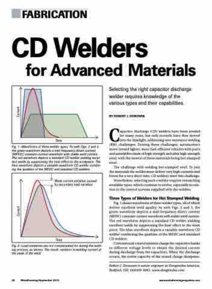
Fig. 1—Waveforms of three welder types. As with Figs. 2 and 3, the green waveform depicts a mid-frequency direct-current, (MFDC) constant-current waveform with stable weld current. The red waveform depicts a standard CD welder yielding excel- lent welds by suppressing the heat effect to the workpiece. The blue waveform depicts a variable-waveform CD welder combin- ing the qualities of the MFDC and standard CD welders.
Selecting the right capacitor discharge welder requires knowledge of the various types and their capabilities.
BY ROBERT J. DONOVAN
Capacitor discharge (CD) welders have been around for many years, but only recently have they moved into the limelight, addressing new resistance welding (RW) challenges. Driving these challenges: automotive’s move toward lighter, more fuel-efficient vehicles with parts and assemblies made of high-strength and ultra high-strength steel, with the newest of these materials being hot stamped steel.
The challenge with welding hot-stamped steel: To join the materials the welder must deliver very high currents and forces for a very short time. CD welders meet this challenge.
Nonetheless, selecting such a welder requires researching available types, which continue to evolve, especially in rela- tion to the control systems supplied with the welders.
Three Types of Welders for Hot Stamped Welding
Fig. 1 shows waveforms of three welder types, all of which deliver excellent weld quality. As with Figs. 2 and 3, the green waveform depicts a mid-frequency direct current (MFDC) constant-current waveform with stable weld current. The red waveform depicts a standard CD welder yielding excellent welds by suppressing the heat effect to the work piece. The blue waveform depicts a variable-waveform CD welder combining the qualities of the MFDC and standard CD welders.
Conventional control systems charge the capacitive banks to different voltage levels to obtain the desired current during discharge from the capacitors. When the discharge occurs, the entire capacity of the stored charge dissipates.
Robert J. Donovan is senior engineer at Dengensha America, Bedford, OH; 440/439-8081; www.dengensha.com
Weld-current variation caused by secondary load variation
Time
Fig. 2—Load variations are not compensated for during the weld- ing process, as shown. The result: variation in welding current at the peak of the weld.
36 MetalForming/September 2019
www.metalformingmagazine.com
Current Current
