
Page 39 - MetalForming September 2019
P. 39
Fabrication: Welding Well
100
50
Constant current 100kA10ms
0 10 20 Time (ms)
Constant current 50kA20ms
With this new control design, users enter weld-schedule parameters with a keypad. Weld current and weld time are simple numeric entries. The weld-current entry, capable of turning off after reaching peak current, saves energy, which can remain stored in the capacitive bank. The result: ener- gy-cost savings and cycle-time reductions due to not having to wait for the entire capacitive bank to recharge.
The variable-wave control becomes possible by utilizing an MFDC to control the discharge of the capacitive bank, combining the best of two worlds: fast welding and the pre- cise control and stable weld strength through constant-cur- rent feedback offered by MFDC technology. The result: excel- lent and repeatable weld quality.
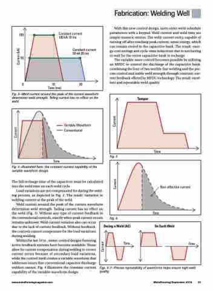
Fig. 3—Weld current around the peak of the current waveform determines weld strength. Tailing current has no effect on the weld.
Temper
Time
Variable Waveform Conventional
Time
Fig. 5
Non-effective current
Time
Fig. 4—Illustrated here: the constant-current capability of the variable-waveform design.
The full recharge time of the capacitors must be calculated into the weld time on each weld cycle.
Load variations are not compensated for during the weld- ing process, as depicted in Fig. 2. The result: variation in welding current at the peak of the weld.
Weld current around the peak of the current waveform determines weld strength. Tailing current has no effect on the weld (Fig. 3). Without any type of current feedback in the conventional controls, exactly when peak current occurs remains unknown. Weld-current variation also can occur
due to the lack of current feedback. Without feedback, the controls cannot compensate for the load variations during welding.
Within the last 10 yr., newer control designs featuring active feedback systems have become available. These allow for current compensation during welding to correct current errors because of secondary-load variations, while the control itself creates a variable waveform that addresses issues that conventional capacitor discharge welders cannot. Fig. 4 illustrates the constant-current capability of the variable-waveform design.
Fig. 6
During a Weld (AC) On Each Weld
Time
Time
www.metalformingmagazine.com
MetalForming/September 2019 37
Figs. 5-7—Precise repeatability of waveforms helps ensure high weld quality.
Current
Current
Current
Current
Current (kA)
