Another powder-bed fusion technology, called electron beam melting (EBM), was pioneered by Swedish company Arcam. EBM employs a high-temperature electronic beam, rather than a laser, to melt the metallic powder.
“The difference between the technologies is that a laser machine can provide 200 to 1000 W of power, while EB machines provide as much as 3500 W,” says Don Godfrey, engineering fellow for additive manufacturing at Honeywell. The company employs Arcam EBM machines at its Additive Manufacturing Technology Center (AMTC) in Phoenix, AZ, one of four AMTCs operated by the company. According to a recent blog post by Godfrey, “Honeywell is developing this technology to reduce capital-tooling budgets and marching it into production to reduce component costs and to improve quality. “After a part is built on a laser machine,” he says, “you can open the door and take it out, much like cooking something in your kitchen—it’s about 200 deg., but you can handle it right away. The electron-beam machine never gets below 1900 F. You have to let it cool down for about 8 hr. before you can take a part out of the machine—and that has to be calculated into your overall production time.”
Printing Larger Parts
Because metallic powders are expensive and heavy, powder-bed fusion technology is limited in the part volume it can print, though each new generation of printers seems to accommodate larger and larger builds. Currently, the largest powder-bed fusion machine available, the X line 2000R from Concept Laser GmbH (U.S. operations are based in Grapevine, TX), offers a build volume to 31.5 by 16 by 20 in.
Anything larger requires some form of direct metal deposition (DMD), a completely different type of additive-manufacturing technology that is not confined to a powder bed. In DMD machines, such as those built by German manufacturer Trumpf, a numerically controlled five-axis articulated laser head continuously traces out a melt pool on a metal base, following a programmed pattern. The printer then sprays metal powder into the melt pool where it cools and fuses with the layers underneath to build up a solid part.
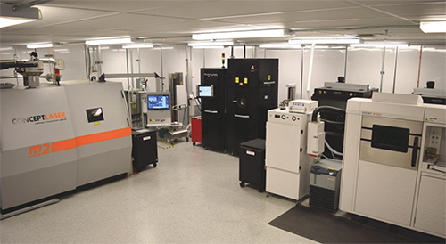 |
| Honeywell employs Arcam electron-beam melting machines and a laser-melting system from Concept Laser in its Additive Manufacturing Technology Center in Phoenix, AZ. |
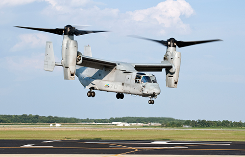
Another type of DMD technology is the electron-beam additive manufacturing (EBAM) system developed by Sciaky (Chicago, IL) to build very large parts. Sciaky uses an electronic beam rather than a laser head to melt a metal filament, which then fuses with previous layers to form a solid piece. Sciaky claims that its machines can make parts as large as 19 ft. long, 4 ft. wide and 4 ft. tall, with unlimited geometry—perfect for a small aircraft wing or airfoil.
Accelerating Production
Metal
3D printing has become a game changer for many aerospace OEMs, by drastically reducing the time and cost to develop prototypes and tooling.
“We spend an enormous amount of money on tooling, and we can improve our manufacturing flowput by printing tooling used internal to Honeywell,” Godfrey says. “Tools that might take six or seven weeks to manufacture can be printed in a day or two. If we can get the right tools to the test rigs two or three months ahead of the original plan, we can save tens of thousands of dollars in schedule and program costs.”
For production parts, metal 3D printing can speed things up even faster by skipping the tooling altogether and instead using 3D simulations and printed prototypes to power through the development cycle. “We completed almost nine different build orientations and designs before we found one that we locked down—in four months,” says NAVAIR’s McMichael. “If you think about typical production tooling, you wouldn’t be able to do that.”
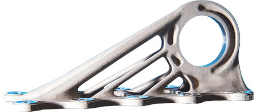 |
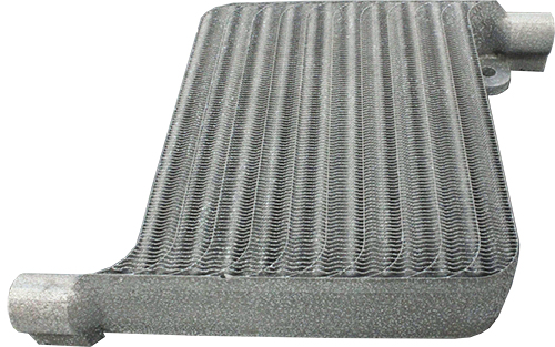
| This titanium-alloy 3D-printed bracket, produced on a Concept Laser machine, is used on the Airbus A350 XWB. It’s significantly lighter than the previous part, milled from aluminum. |
The first time the team went through the development process from concept to demo took more than one year, McMichael adds. “But because of what we’ve learned, we think can go faster for some of the other parts we’re choosing, particularly for parts made of the same material and using a similar process.”
Revolutionary Designs
One of the first valid uses for metal printing at NAVAIR was building replacement parts no longer available for older aircraft. Only after this issue has been addressed successfully will McMichael’s team pivot to the next priority: using AM to improve Navy and Marine Corps aircraft by making parts lighter, adding new capabilities, or combining multiple parts into single assemblies to improve cost and reliability, McMichael says. The high cost of aerospace materials makes it imperative to minimize the amount of material lost in production. To gauge the amount of waste in the process of making parts, aerospace engineers calculate the ratio between the weight of the material used to make a component and the weight of the component itself—the ‘buy-to-fly’ ratio.
The ideal buy-to-fly ratio would be “1,” indicating no loss of material during manufacturing. With 3D printing, the amount of wasted material allows manufacturers to approach a buy-to-fly ratio of 1, because any powder left over after printing can be re-used. This not only slashes material costs, but also improves sustainability.
|
|
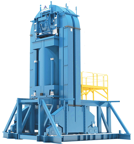
| Alcoa has invested $22 million in its Whitehall, MI, facility to expand its capabilities to perform hot isostatic pressing of larger 3D-printed metal jet-engine parts. The process improves the mechanical properties of 3D-printed parts made of titanium and nickel alloys. |
Even more important than sustainability and reduced material cost is energy efficiency, required to help manufacturers meet ever-stricter environmental regulations. It also helps to reduce fuel costs—and the number one way to improve efficiency is to reduce the weight of the plane.
To achieve ultimate weight reduction requires an entirely new approach, focusing on the design itself rather than the traditional “design for manufacture,” which optimizes the ability of existing tools and processes to make a component. The 3D-printing process makes possible entirely new geometries and topologies, including more organic, or “bionic” designs that never could be realized with subtractive manufacturing.
Printing Aerospace Materials
In addition to lighter-weight designs, lightweight materials also are essential to reducing the amount of fuel required to fly an aircraft. Aluminum is light in weight and relatively inexpensive, and in addition to wings and airframes, also can be used for smaller non-critical parts such as air-handling systems.
By itself, aluminum has a very low melting temperature and high ductility, so for advanced aerospace applications it often is mixed with other metals to improve overall powder (and part) characteristics.
One of the most common aluminum alloys is Ti64, the material used for the new NAVAIR 3D printed part. Ti64 has a high strength-to-weight radio and fatigue resistance, as well as improved resistance to corrosion and high temperatures.
Last year, Honeywell became the first company to 3D-print an aerospace component—an experimental design of an existing tube used on its HTF7000 engine—with the nickel-based superalloy Inconel 718. Honeywell, via its AMTC labs, is dedicated to 3D printing nickel materials, including Inconel 718, Inconel 625 and Mar-M 247. Inconel, a blend of nickel mixed with chromium, molybdenum and niobium, can stand up to the extreme heat and high pressures inside of a jet turbine. The nickel component enhances the corrosion resistance of the alloy, another important characteristic in the extreme temperature environment of the combustor.
Following the success of its first Inconel 718 part demo, the company has begun to produce another part, a rear bearing turbine support, printed with the same material. In order to fly a 3D-printed component on a commercial airplane, even a relatively insignificant part, the FAA must first approve the metal powder that will be used, as well as the part itself.
|
|
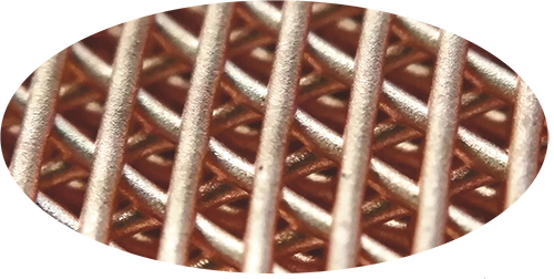
| Researchers at Northwestern University recently printed this copper lattice structure using a new room-temperature metal-printing process that appears to provide the ability to produce completely novel structures for aerospace applications. (Photo: Dr. Adam Jakus, Northwestern University |
“We have to select a powder vendor, and then audit that vendor to Honeywell quality standards,” Godfrey says. “Then we must document how the powder is to be received, stored, loaded into the printer and reused after a build. All of that information must be submitted to the FAA.”
Honeywell plans to use its certified engineering-design data (EDD) lab in Bangalore, India, to help test and develop new powders, so that data can be used in the engineering design of a component. In addition to testing the powder, getting a printed component approved takes months and involves printing more than 1000 test bars that must undergo tensile and life-cycle testing, Godfrey adds. Then, several parts must be built and bolted to engines on test stands and flight test beds.
Processing and Heattreatment
Printing parts isn’t the end of the story—post-production processes also come into play.
“There’s still a lot of milling, lathe work and grinding to do on printed metal parts, depending on the part being made,” says Tim Simpson, professor of mechanical and industrial engineering and engineering design at Pennsylvania State University. Simpson also is co-director of the Penn State Center for Innovative Materials Processing through Direct Digital Deposition, which helped NAVAR print its first parts.
Though the high-temperature EBM process eliminates residual stresses, most metal 3D-printed parts will require heattreatment in an oven to relieve stresses in the material, Simpson says.“
As you’re printing the part, it builds up stresses internally, and at a minimum you need to stress-relieve the part so that when you cut it off the build plate, it won’t warp or crack. And, often heattreatment is needed to obtain the required micro-structure,” Simpson says. “The cooling schedule may be critical, to achieve the correct microstructure and properties.”
Another post-processing step used particularly for 3D-printed metal aerospace components is hot isostatic pressing (HIP). This process simultaneously applies heat and high isostatic gas pressure to printed parts to improve their mechanical qualities. Alcoa pioneered the use of HIP technology for aerospace applications in the 1970s, for use with cast parts.
“During HIP,” explains Simpson, “the part is heated and essentially squeezed, which rearranges the material at the molecular level. The resulting phase transformations provide a different crystal growth structure that eliminates any voids or defects. The result is improved fatigue strength and prolonged part life.”
Future of 3D Printing
It’s safe to say that metal 3D printing is revolutionizing the aerospace industry. All of the major players are printing, testing and beginning to fly 3D-printed parts. Meanwhile, new technologies and materials for metal aerospace printing continue to advance, along with a better understanding of how the printing process affects the mechanical properties of a part.
“Right now everybody in the industry is printing powders that have been around for 20 years, because it’s a new technology. When you change to a new powder you’re adding another unknown,” says Honeywell’s Godfrey. The company has some 40 new types of metal powders it hopes to test for 3D printing.
As new and different alloys and superalloys become available, companies will have more options to create parts with unique material properties, even within the same part. Before that can happen, part designers must be able to understand exactly what occurs during a print, at the micro or nano scale.
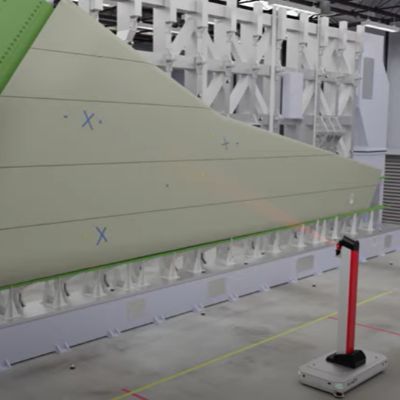
“We’ve got some unique capabilities for modeling the actual printing process itself, and understanding how much a part is going to deflect as it’s built,” says Penn State’s Simpson. For example, a colleague of Simpson’s, engineering professor Pan Michaleris, is modeling a 10-ft. wing printed with a Sciaky EBAM system, funded by the Air Force Research lab. The goal is to learn how the wing distorts due to heating and cooling of the metal deposition, and how to mitigate the distortion.
The future of 3D metal printing for aerospace also may include new technologies, like the room-temperature metal ink-extrusion process pioneered by Ramille Shah, assistant professor of materials science and engineering, and her team at Northwestern University. Using a 3D bio-plotter system developed by EnvisionTec—the same type of extrusion printer used to build biological-tissue scaffolding—Shah and postdoctoral fellow Adam Jakus are printing with a liquid ink made of metal or mixed metal powders, combined with solvents and an elastomer binder. The printing takes place at room temperature, and afterward the structures are heated in a simple furnace where the powders fuse together and the binder melts away, leaving a solid metal part.
The exciting aspect of the new technology is that after the object is printed, the structure remains flexible due to the elastic polymer binder. This allows it to be manipulated before being fired. According to Shah, the process potentially could be used to 3D-print full sheets that are meters wide, which then could be folded into large structures, with the only limitation being the size of the furnace.
These and many other advances may someday result in cheaper, faster and more uniform processes and materials for 3D printing of metal parts in the aerospace sector. 3DMPIndustry-Related Terms: Alloys,
Bed,
Case,
Center,
Corrosion Resistance,
Ductility,
Form,
Gauge,
Grinding,
LASER,
Layer,
Plate,
SurfaceView Glossary of Metalforming Terms
See also: Sciaky Inc, Concept Laser GMBH, Arcam AB, Alcoa
Technologies:


 Holly Martin