A Complex Design
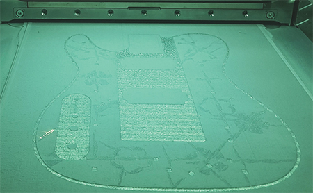 |
| Fig. 2 |
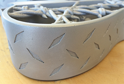
The journey began by developing a sufficiently complex guitar design that would be impossible to produce using conventional methods of manufacturing, while symbolically representing metal (e.g., barbed wire). The inspiration was a Fender Telecaster design, modified by replacing the outer body with a diamond tread-plate design. The front and back surfaces were created (using SolidWorks, Fig. 1) with crisscrossing strands of barbed wire. To soften the design, a few roses were added to the inside of the guitar to counteract the hardness of the outer design.
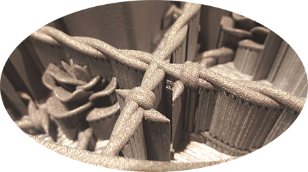 |
| Fig. 3 |
From a DfAM perspective, the thickness of the outer body and the strands of barbed wire must be strong enough to withstand the abuse that guitars often encounter. A 10-mm-dia. curved pipe allows wires to run from the main body to the electronic cavity, under the assumption that it could be printed without the use of support material on the inside. (It was known that the limits were being pushed because most pipes with a diameter larger than 6 mm require support material, unless they are teardrop-shaped).
Also, the angles of the rose petals, wherever possible, were designed to be greater than 45 deg. in order to minimize the need for support material. From a usability perspective, all barbed-wire spikes were designed to point inward to minimize the risk of injuring the musician. To minimize weight, a wooden core was used inside the main body of the guitar.
Time to Print
After completing the CAD design and saving the work in STL format, the file went to Xilloc, a Dutch company enlisted to produce the guitar. Using an EOS M 400 machine, Xilloc printed the guitar body using AlSi10Mg aluminum. The powder-bed fusion system spreads layers of metal powder and employs a laser to draw slices of the CAD model onto layers of the powder. Wherever the laser strikes the powder, the material fuses and bonds to the previous layer, with the rest of the material remaining in powder form. The process repeats, layer upon layer, until the entire part is complete.
After removing the loose powder, the remaining part is attached to the machine’s build plate. This makes metal powder-bed fusion systems vastly different from polymer-based powder-bed fusion systems. With polymer systems, the unmelted powder supports any overhanging part features. After printing, the powder is removed and the part is sand-blasted to clean the surface. With metal AM, support material (Fig. 3) anchors the overhanging features (those exceeding around 45 deg. from vertical, depending on the material being used). Rather than supporting the overhanging features, the support structures serve to remove heat from the part, secure it in place, and prevent distortion from heat-related stress in the part.
Effectively, the entire part is welded to the build plate and support material is used where required. The first step after printing, then, is to remove the part form the base plate, often accomplished using wire-EDM or with a bandsaw. (Often, parts undergo thermal stress relief prior to removing them from the build plate, to help prevent distortion and warping.)
Delicate, Challenging Support-Structure Removal
After removing the part(s) from the build plate, the support structures must be removed. This is where most of the post-processing time is spent. For the guitar, support-structure removal took more than four days using a combination of methods and tools, including long-nose pliers, mallets and chisels, screwdrivers, tweezers and dental picks. The supports between the rose petals, in particular, proved difficult to remove due to limited access. And, the top surface of the guitar required milling to remove the coating of support material. (Xilloc printed two guitar bodies, and removing the support structures from the second body took just 1.5 days).
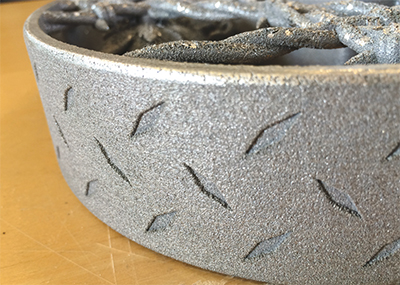
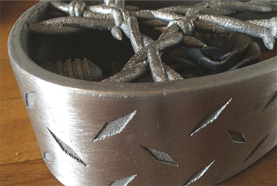
 The arduous task of improving the surface finish came next. Straight off of the AM system (Fig. 4a), the surface finish could best be described as similar to a sand-cast part. The goal was to produce a much smoother finish, accomplished using a lot of filing and sanding (Fig. 4b), followed by shot-peening with glass beads to give the guitar a soft satin finish (Fig. 4c). This step also took 3 to 4 days, mainly because of the geometric complexity of the guitar. In contrast, the second guitar took less than 2 days to achieve the same level of finish. A lesson learned from this project is to think of metal AM in the same way as sand-casting—all surfaces that require a good finish must be machined in a post-processing operation.
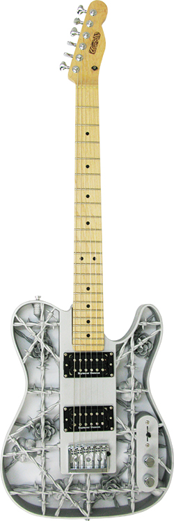
Finally, the guitar was assembled (Fig. 5) by CNC-machining the wooden inner core and assembling the core into the aluminum body. The neck was attached, the pickups and electronics were installed and wired, and the back plates were laser-cut and engraved.
Lessons Learned
So, what lessons were learned? For one, this project reinforced the strong belief of what is possible with metal AM. It also reinforced the importance of post-processing, and recognized the amount of labor required to finish metal-AM parts. This project also demonstrated the need to design specifically for maximizing the benefits of metal AM while minimizing the amount of required post-processing. Substantial changes to the guitar design have since been made to reduce the amount of needed support structures.
The best way to design for AM is to gain a deep understanding of the setup and operation of the AM system itself. This means direct hands-on experience with the machine (not possible for this project). Designing the part correctly in the beginning lessens the number of decisions to be made by the machine operator, such as where to put support structures, which may affect the quality of the finished product. 3DMP
Industry-Related Terms: CAD,
Core,
Draw,
Form,
LASER,
Layer,
Model,
Plate,
Point,
Run,
Surface,
ThicknessView Glossary of Metalforming Terms
See also: Solid Works, EOS of North America, Inc.
Technologies:


 Terry Wohlers
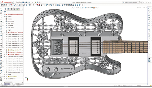

 Video
Video
 Event
Event