Eren Billur Eren Billur
Technical Manager

Digital Image Correlation: How It Changed the Tensile Test

January 30, 2020
0
Comments


For metal formers, one of the simplest and oldest tests is the tensile test. In the simplest form, a tensile test machine must record elongation of the test specimen (Δl) and the reaction force (F) multiple times during the experiment. The recorded data then are used to calculate material properties such as elastic modulus E, also known as Young’s Modulus), yield or proof strength (YS, σY, Rp0.2, or RE); and ultimate tensile strength (UTS, σUTS, Rm). A tensile test also can determine total elongation (TE percent, A percent, A80, A50 and similar), where the numbers indicate the initial gauge length in mm, but its measurement/calculation depends on the test equipment.


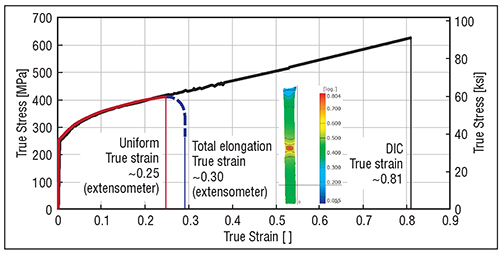
True Stress-Strain curves of BH220 steel 2 determined with mechanical extensometer and DIC. Image courtesy of At??l??m University Metal Forming Center of Excellence in Ankara, Turkey—The author thanks research engineer Türkay Muratoglu for his support.
Although the tensile test has been around for many decades and its basic principles haven’t changed, there have been dramatic improvements in data-acquisition systems and controls.1 In addition, metal formers would like to obtain more information from the simple tensile test. While measuring and recording force is relatively simple using load cells, measuring elongation can present challenges. Older machines may still use crosshead displacement for calculating yield and tensile strength values that do not require precise elongation data. However, these machines cannot precisely calculate elastic modulus. For total elongation (elongation at break), one can mark the initial gauge length and then measure these marks.

Improvements to tensile test machines started with the introduction of an axial extensometer, a delicate clip-on sensor, with knives on the edges, designed to provide precise measurement of the extension. Instead of relying on crosshead displacement—where frame deflection and slipping of the test specimen can impact accuracy—an extensometer measures elongation of the gauge. Adding an extensometer allowed engineers to precisely measure a material’s elastic modulus and uniform elongation (Ag).

Note: Extensometers are relatively delicate—it is typically advised to remove them before fracture.

By the 1940s, after earing and deep-draw problems had been studied and researchers developed what we now know as r-values (plastic anisotropy coefficients or Lankford parameters), engineers understood that material tests require the simultaneous measurement of length increase and width decrease—achieved by transverse strain measuring. Some extensometers can measure width strain, and, therefore, enable calculation of r-value and Poisson’s ratio.

The 1980s welcomed the introduction of video extensometers for tensile testing. With a tensile specimen marked with a dot pattern, a camera records movement of the dots during the test, and calculates the average length and width strains. This allowed researchers to measure total elongation without user intervention.

Even with the video extensometer, true stress and strain could only be determined until necking. Enter the noncontact measuring technique called digital image correlation (DIC), which, by using a camera setup and software, allows engineers to measure strain in both directions (longitudinal and width) for small facets. Using DIC, we can develop the stress-strain curve after necking. And, contrary to other systems, DIC simplifies strain testing but complicates stress calculation. Longitudinal and width strains can be calculated directly, and when known allow calculation of thickness strain from volume constancy, and then the instantaneous cross-sectional area. Thus, we can calculate the true strain when we know the force at this time increment (σ=F/A).

As an example, consider the results of an experimental study (see the accompanying figure, page 32) with a bake-hardenable steel, 220-MPa yield strength. Testing with a mechanical extensometer revealed a 28-percent uniform elongation (Ag) and 35-percent total elongation (A80). In true strain, these numbers correspond to 0.25 and 0.30, respectively, so a true stress-strain curve with the extensometer only gives valid data until 0.25 true strain (the red curve in the figure). Conversely, testing with DIC enabled measuring true strain until 0.81.

Still, most steel standards rely on extensometer data with a given initial gauge length (50 or 80 mm). However, DIC data can reduce the error in stress calculation due to extrapolating the tensile data. Further, the maximum DIC strain can be used to predict local formability problems such as hole-expansion ratio.

Next time, I’ll discuss using DIC for developing a forming limit curve and for conducting a bulge test.

1 In a recent effort to find out the oldest tensile test machine still in service, a hydraulic tensile test machine from 1876 was selected.

2 Commonly known as BH220. HC220B according to EN10268—similar to SAE J2340-210B. MF

Industry-Related Terms: Gauge, Tensile Strength, Thickness, Forming, Center, Form
View Glossary of Metalforming Terms


See also: Billur Metal Form

Technologies: Quality Control

Comments

Must be logged in to post a comment.
There are no comments posted.

Subscribe to the Newsletter

Start receiving newsletters.