The ANSI Z244.1 subcommittee has
detailed that the risk-assessment process as prescribed in ANSI B11.0 is used
to determine if an acceptable risk can be achieved by applying an alternative
method to complete specific tasks, instead of following the requirements for
lockout to perform said tasks.
A risk-assessment document provides the steps needed to bring s piece of equipment into compliance, per the appropriate ANSI and OSHA codes. The assessment considers all aspects of the safety system, as discussed in a previously published MetalForming article.
The risk-assessment documentation should
be reviewed as part of the overall safety-system review.
Implementing the Alternative Method
The press slide/die-area space presents numerous opportunities for personnel to interact with equipment, and those tasks cannot always be completed by following OSHA 1910.147/ANSI Z244.1, hazardous-energy-control lockout methods. Unfortunately, far too often the analogy of having the “cart before the horse” occurs as the alternative method is implemented without following the requirements noted above regarding the use of alternative methods as prescribed in Z244.1:
- A practicability/justification analysis
- A risk assessment
- Other applicable evaluations as detailed in clauses
in the standard.
The above documentation, along with
the properly designed and validated safety-control circuit, provides the
defendable information to justify not following the hazardous-energy-control
lockout methods. Only after completing
this documentation and analysis should a stamper implement an alternative
method.
Given that the tasks involve the press
control, it also is typical that the emphasis on circuit analysis focuses on
the clutch/brake or servo-drive control for the press only, without properly
considering that multiple pieces of equipment, under different control systems,
exist in the same shared space where operators are completing tasks. This shared space is where ANSI B11.20, and
the other B11 standards noted, provide requirements and guidance on how the
various safety-control systems, and the safety-related devices, must be
integrated together to provide the proper safety-circuit performance to meet
the requirements of a documented task-based risk assessment.
Note: Simply placing the press (and
related equipment) into a manual operating mode is not in itself an example of
a properly implemented alternative method.
Manual mode, by itself, is not a safety circuit and does not prevent
unexpected motion, nor can it meet the OSHA requirement of effective protection
needed to justify the task being performed in lieu of lockout. This would not meet the analysis required in
a documented risk assessment for appropriate risk-reduction methods for those
tasks, nor the requirements of a control circuit providing for alternative
method hazardous-energy control. The
addition of some simple safety circuits can easily be provided, but without the
review and planning process completed during the risk-assessment phase of a
project, it becomes more costly as an afterthought and can lead to other hidden
or future costs.
While
a transfer press often is thought of a shared-space application, other examples
include tandem-press lines with various types of press-to-press automaton,
including robots; blanking-press lines with coil-feeding and stacking
automation; progressive-die coil-fed press operations; and automated presses
with blank-destacking/feeding equipment.
Exclusive
Control
To
simplify the use of an alternative method to control all of the unexpected
motion of the press and automation equipment, we suggest the use of an
exclusive control device as part of a properly designed safety-control circuit.
The circuit should be designed to ensure the interlock of all of the various
control systems found within the shared space. Providing someone with exclusive
control of the safety-control circuits for the press and related equipment
ensures that no one else can reset the safety system without their knowledge,
and prevents unexpected hazardous motion while that person interacts with the
equipment to complete a task. Examples of an exclusive control device that can
be designed into a properly designed safety circuit include, but are not
limited to, safety Interlocking switches, safety interlocking key switches,
trapped key systems, electronic tag/fob safety-rated devices, and safety-rated
enabling devices.
Also required: an analysis to clarify
the span of control of the exclusive control-safety devices used, to help in detailing
the interlocks to the other control systems that are not part of the press-control
system. ANSI B1.20, ANSI Z244.1, and
additional B11 Standards such as B11.0, B11.19, and B11.26 all provide
guidance, as well as the C level standards for the equipment such as B11.1,
B11.2, B11.3 and B11.18 for proper implementation of the performance of the
various safety functions.
Safety-Related Parts of the Control
System
Metal formers must understand that the
circuit must be more than just the exclusive control device and its application
to the press safety-control system. The
device must be part of all safety-control systems responsible for the control
of hazardous energy, and each of those systems may include multiple safety
functions that the exclusive control device must be part of, as a detecting
device within the safety function.
Each safety function contains a minimum of three elements, as shown here.
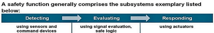
Note: Each safety function must be analyzed to determine the
architecture (category level) for that specific function. Performance levels and control-reliability
analysis also can be used for the analysis.
As previously noted, the OSHA interpretation for recognizing “properly designed safety-control circuits that provide effective protection for control of hazardous energy when using alternative methods for tasks” is based on the accepted methodology of the ANSI term control-reliable safety circuit. Per ANSI B11.26, a control-reliable safety circuit is a minimum of a category 3 circuit architecture--an architecture or design where “no single failure will cause the loss of the safety function.”
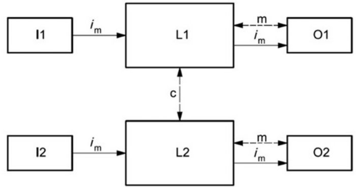
Per ANSI B11.26, the requirements for achieving
a category 3 circuit (see the diagram below):
Safety-related parts
of the control system of category 3 shall be designed so that a single fault in
any of these parts does not lead to the loss of the safety function. Whenever reasonably practicable, the
single fault shall be detected at or before the next demand upon the safety function:
- when
the single fault occurs the safety function is always performed,
- some
but not all faults will be detected,
- accumulation
of undetected faults can lead to the loss of the safety function.
- Note – item iii above is one of the reasons we perform documented periodic checks at regular intervals, the interval period determined by a risk assessment.
In Summary
… the review for applications of alternative methods for the control of hazardous energy in lieu of lockout for press-related equipment serves as a reminder to not overlook the responding element of the above diagram. That responding element for this type of equipment includes motorized control as well as fluid-power control. Too often, what looks like a proper safety device utilized for exclusive control is not properly designed within a control circuit that includes the responding unit, that being the element that can cause unexpected hazardous motion. Only by following all of the requirements within the ANSI documents discussed above can an effective alternative method be implemented, and then proper validation must occur to ensure that all of the requirements, and the risk-assessment analysis, have been met.
Also, while the above information is based on providing a safety-control circuit only for the alternative method control of hazardous energy, realize that at times a combination of both a safety-control circuit and an additional isolation method can be used, especially when dealing with fluid power, until acceptable methods of control circuits can be fully implemented. MF
See also: White Horse Safety, Inc.
Technologies: Safety


 Webinar