 Designing for the Additive Process
The design process for additive manufacturing often begins with an existing design, especially when the goal is to remove cost or weight from a current product. The part-selection process, material decision and technology down-select could represent an entire discussion and article on its own. But let’s fast-forward to after those decisions have been made when it’s time to open a CAD package and create the additive design.
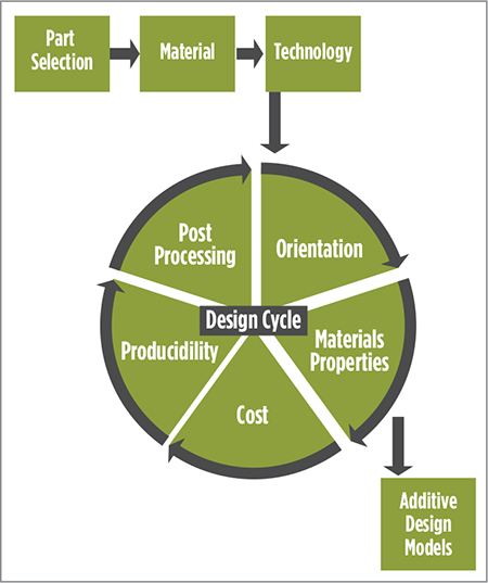
The design cycle is not linear. Decisions made during each design stage will affect and contribute to others.
The cycle has many possible outcomes depending on what parameters must be optimized. For example, a one-off development piece where lead time represents the most important factor may lead to a flat and low orientation, which reduces build height and does not consider the quantity of parts that can nest together in the build box.
 This would be inefficient in a production environment because the number of builds required to meet production quantities would increase with labor costs for setup and tear down, build-to-build consumable costs and machine downtime between builds. The one-off development-piece design will be completely different than one that optimizes for a production volume that maximizes parts per build, nests multiple layers of parts and reduces post-processing steps via unique features.
Investigating each of these puzzle pieces separately is difficult because they are related by cause and effect. However, some basic guidelines and considerations should be drawn upon when in the design cycle.
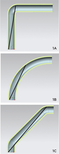 |
| Fig. 1—Depicted are examples of line-of-sight powder removal: A) simple radius B) elongated radius C) straight center with radii on exits. The black lines show how far the compressed air in the powder-recovery system can reach into the cavity line of sight. It is not always intuitive as to which geometry would be best for powder removal. |
Material Properties Differ
Properties of additive-manufactured alloys are not equivalent to those of wrought or cast alloys. Additively manufactured materials have their own design system, and should be treated as such. Due to temperature gradients encountered during the additive-manufacturing process, material properties and microstructure can be anisotropic in nature prior to post-process thermal treatment. Thermal processing can alter the microstructure to become more isotropic, but some orientation and geometric effects may remain. The effects may be seen on monotonic or dynamic properties.
It’s important to understand how significant the effects are within the material/ process combination chosen. If there are design features that would be limiting if not built in a certain direction, the design engineer should integrate that design rule into the beginning stage of orientation decisions.
Consider Post-Processing
Two types of CAD models exist for additive manufacturing. One is the final geometry, to which the final produced part will be inspected. Datums are identified, machined tolerances called out, surface-finish requirements zoned, etc.
An equally important CAD model, the as-built model or the model input into the additive machine, appears differently than the finished models. Holes may be filled in, support structure added, machining stock added and more. To understand the considerations placed into the as-built model, a generic process map is provided.
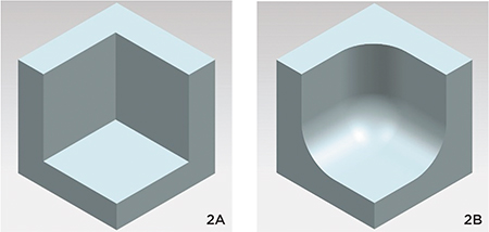 |
| Fig. 2—Designing large radii (2a) instead of corner points (2b) allows for easier powder removal due to a smooth surface rather than a surface with many discontinuities. |
The required post-processing steps appear slightly differently depending on the material and technology used. For example, electron-beam melting (EBM) does not require stress relief or mechanical removal of parts from the build plate, but does require removal of the partially sintered powder surrounding the parts. Laser powder-bed fusion (LPBF) requires stress relief and either a wire-EDM or a band-saw procedure to remove parts from the plate. Thermal processing for all 3D metal printing often includes hot isostatic pressing (HIP) to reduce voids and porosity within the material, with parameters based upon material choice. Additionally, some materials may require heattreating to achieve the desired microstructure.
Advantages, Disadvantages in Build and Powder Removal
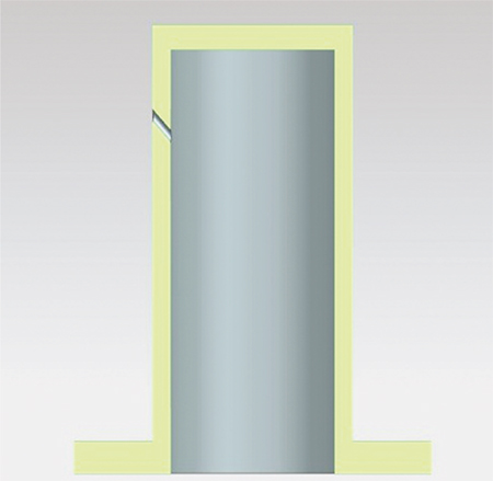 |
| Fig. 3—If internal cavities are buried within the support structure of a part or cannot be reached by the vacuum, powder-removal options must be designed into the parts. If an orientation cannot be constructed to allow for full powder removal, it is common to add holes to the as-built model (upper left) to ease the removal from cavities. These holes then can be plugged by welds. |
Additive technologies offer certain advantages and disadvantages related to build and powder removal.
Electron-beam melting (EBM). Best practice is to not build directly on the plate, especially if the parts have strict composition requirements. The stainless-steel plate may influence the first few layers of the build, so start parts at least 3 to 5 mm from the top of the build plate. That 3 to 5-mm area can be filled either by support structure or solid material to be later removed, whichever is more efficient for the part. One advantage of the EBM process: Due to low residual stress from the entire build area at elevated temperature, fewer supports are required and the parts usually pop off of the plate easily.
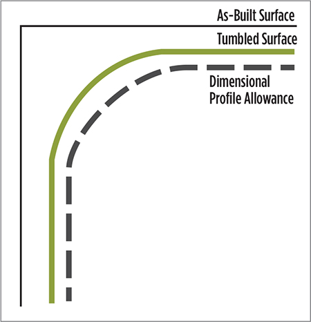 |
| Fig. 4—When attempting to compensate for surface-finish methods, designers must consider the physics of the process itself. For example, corners will exhibit a more aggressive material-removal rate than flat surfaces in a vibratory bowl, so profile tolerances may have to be opened (dashed line) in those locations. |
Powder removal represents the greatest consideration during part removal in an EBM build. On one hand, the preheat step in the EBM process provides better part integrity, but for powder removal it provides a challenge. During the preheat step, powder surrounding the solid material is partially sintered, sometimes making it difficult to remove from long cavities. This partially sintered powder does not flow, but the powder must be removed before any thermal part processing, such as HIP or heattreatment. Designing sweeping radii while maximizing line-of-sight cavities into a part makes powder removal more successful (Figs. 1 and 2).
Laser powder-bed fusion. Laser systems offer a benefit in that the powder does not become sintered, and thus flows easily. When intricate interior cavities are required, the removal process in laser provides an advantage. However, even though the powder flows more easily out of cavities, the powder must be removed before stress relief and before the parts can be removed from the plate. Therefore, if the internal cavities are buried within the support structure or cannot be reached by the vacuum, powder-removal options must be designed into the parts. If an orientation cannot be constructed to allow for full powder removal, it is common to add holes to the as-built model to ease the removal from cavities (Fig. 3). These holes then can be plugged by a weld.
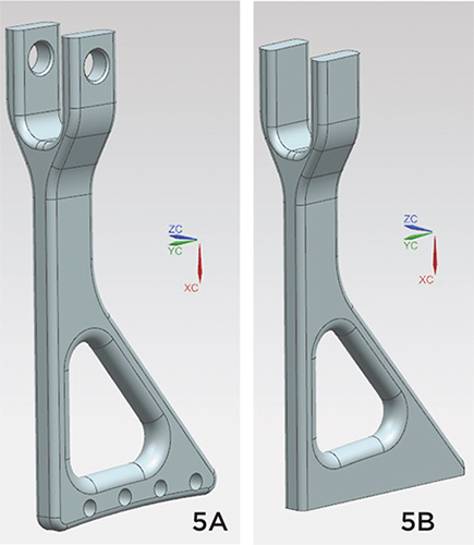 |
| Fig. 5—You can see the difference between final
part geometry (a) and as-built geometry (b) with holes filled in and
bottom stock added for post-process machining. |
In laser systems, parts and the plate essentially are welded together, adding complexity to part removal and adding time to the overall process. Parts must be removed by mechanical methods such as wire-EDM or a bandsaw. Wire-EDM is a more accurate process, so the additional stock needed underneath the parts may only be 3 mm thick, whereas with the band saw it is recommended to add at least 5 mm underneath the solid material or support structure.
Consider Thermal Processing
Thermal processing in most cases does not define or change many designs, unless significant distortion during the thermal process occurs due to drastically varying thicknesses compared to part length or height. This is another area where choosing the right additive technology proves beneficial. Large parts can be difficult to produce on laser systems due to the “cool” process that is challenged by residual stress. Most laser builds require stress relief, but even more so on parts that span the build area.
EBM may be a better choice in general for large parts in both the horizontal and vertical orientations, because the stress-relief step is not required. If geometric distortion is still an issue for a part, a few options can help it hold its shape through thermal processing. For instance, adding a sacrificial gusset or frame around thin-walled components can provide stability during thermal processing.
Compensate for Surface-Finish Needs
Printed parts exhibit rougher surface finish than castings when using powder-bed-fusion technologies, and finish also depends upon the orientation of the part surface. Top surfaces can be fairly smooth, vertical surfaces normally have a rough but consistent finish, and surfaces orientated at angles less than 90 deg. from the build plate can be the roughest. Generally, laser powder-bed systems have optimized powder and laser parameters that enable a smoother surface finish. EBM has focused on optimizing for cost via build speed, and therefore surfaces generally are rougher—a build-time trade-off.
Keeping surface finishes as-built is optimal for cost, but structural and flow requirements or part aesthetics can drive the need for various surface-finish methods. Here, the ultimate goal is to understand the material-removal rate and compensate for that in the as-built model. For example, if a tumbling process removes 0.005 in. from the surface, add a 0.005-in. envelope to the as-built CAD file so that, following post-processing, the features will conform to required thicknesses.
When attempting to compensate for surface-finish methods, designers must also consider the physics of the process itself. For example, corners will exhibit a more aggressive material-removal rate than flat surfaces in a vibratory bowl, so profile tolerances may have to be opened in those locations (Fig. 4). For critical features or tolerances, different masking techniques during the surface-finish process may aid in maintaining the as-built surface so that material does not degrade, or can be machined later.
In addition to external surface-finish methods, internal cavities often require finishing to smooth channels for flow requirements. Similarly, designers must consider the material-removal rates of those methods and compensate for them in the model.
Design for Machining
As discussed previously, most parts must be machined before becoming final products. Critical features and tight tolerances that can’t be achieved by the printing process usually must be brought into conformance by conventional CNC processes. Design considerations up front make the CNC process more effective.
Design and manufacturing engineers should collaborate to understand how the part will be held during CNC-process setups. Utilizing advantages of additive manufacturing, datum features can be added to the as-built model to reduce custom tooling, or at minimum provide consistent tooling across a part family of similar geometries. Tabs, pins, holes, slots or even a temporary handle can be added to the printed part to help align any fixtures and tooling, and can be later cut off. Having such conversations up front reduces development iterations and quickens setup and development time.
Wrap stock represents another design consideration with regard to machining. Just as with surface finishing, some material removal is required to bring critical tolerances into conformance. Adding wrap stock to those features ensures an adequate amount of material for removal via the CNC process. The amount of wrap stock added should be enough to compensate for removal but still hold tolerances, and limited so as to not add excessive time and cost to the CNC process. This varies depending on the material, part geometry and the CNC technology used (Fig. 5).
Not Your Father’s Design Process
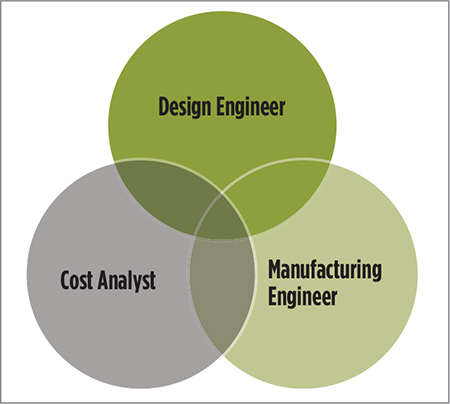
In summary, additive-manufacturing designers must wear multiple hats. They must understand the full manufacturing value stream, cost analysis, and even structural and materials engineering. One step better: Have experts available in a collaborative atmosphere to provide insight into the design process as it proceeds. 3DMP
Industry-Related Terms: CAD,
Center,
CNC (Computer Numerical Control),
Corner,
Datum,
Form,
LASER,
Lead Time,
Lines,
Masking,
Model,
Plate,
Surface,
Wrought,
AlloysView Glossary of Metalforming Terms
See also: LAI International Inc, Arcam AB
Technologies:


 This new idea of starting from nothing instead of from a block of material, while overwhelming for some, becomes limitless for students and young design engineers without decades of strict rules and guidelines filling their heads. However, the fast pace of additive-manufacturing adoption requires those who previously trained for conventional design to rapidly retrain and rethink the way they design to meet the vast new options afforded by additive. It’s important to realize that while “complexity is free,” there are still guidelines and instruction that can make your additive design the most efficient when considering the parameters of cost, time and quality.