Support Structure
 |
| As designers become familiar with the process, machine and material, they can begin to develop custom support structures—options include use of angling and floating supports, and adding sacrificial materials for thermal consistency. |
Support structure can make or break the effectiveness of utilizing AM over other conventional fabricating methods. Most machine OEMs provide default parameters for support structure, established to accommodate the largest array of geometric features with the least amount of effort by the designer. Unfortunately, for most process-material combinations, there is a sweet spot for support structure depending on the geometry; but, blindly using these default supports does not always produce sound and efficient results. Consider the following factors when studying and designing support structures:
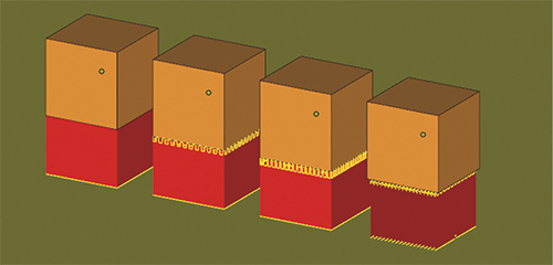
Hatch density: For ease of powder removal, as well as support removal, a coarse support structure is favorable. In addition to aiding in the post-processing efforts, reducing support structure may also slightly reduce build time since there is a decreased amount of cross-section melting at each layer. Although post-processing efforts favor a coarse support structure, the parts themselves sometimes favor a fine support structure. Bulk melt parameters, and consequently bulk material properties, are based on material that has full connectivity and conduction to the previously melted layer. When the previously melted layer is support structure, the amount of conduction of heat away from the layer is decreased, which can cause the layer to overheat and swell. Therefore, sometimes a fine support structure can help because it behaves more closely to the optimized bulk material.
Support/part interface geometry: It’s also common to see an influence of support structure in the transitioning layers between support and bulk material. The influence can be on surface roughness and geometric accuracy, as well as on microstructure and opportunities for voids or other material defects. The connection geometry between the support structure and the component can be varied to identify the optimal setting, but melt parameters of the transition layers also may need to vary in order to find the optimum settings.
Minimum overhang angle: Establishing a minimum overhang angle that provides consistent geometric accuracy without over-supporting curved surfaces is a fairly straightforward rule that is usually accurate as provided by the machine OEM in the machine’s default parameters. But, depending on the geometry, the support angle may need to increase or be allowed to decrease, while providing the same geometric accuracy results post-build.
Minimum surface area: It’s always a good idea to find out how far you can push certain geometries, such as overhang sizes and hole diameters, before adding the support structure. It’s not uncommon to be overly conservative for a one-off build component; however, for a component that will be produced in a high-volume production setting, reducing unnecessary supports will make post-processing more efficient.
Custom supports: As AM designers become more familiar with a certain process, machine and material, they can begin to develop custom support structures to increase build efficiency, minimize post-processing costs and optimize thermal stability. Options include use of angling and floating supports (common with electron-beam melting) and adding sacrificial materials for thermal consistency.
Note: When investigating support structures, try creating demo parts using different types of geometries built with various support parameters. This learning process allows designers to create custom supports for components without relying solely on default methods.
Layout and Orientation
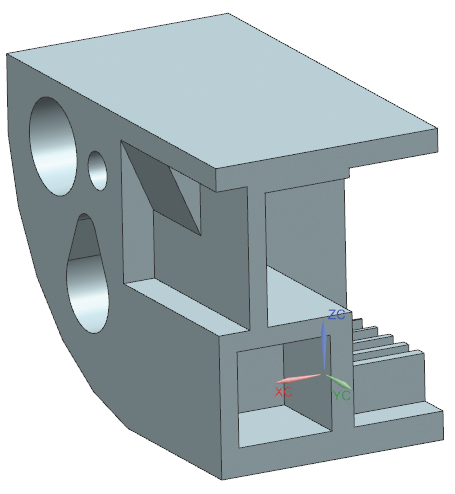 |
| A good option when trying to learn about support-structure specifics is to create a demo part, similar to that shown here, where different types of geometries can be built with various support parameters. The learning from such a study allows designers to create custom supports for components without relying solely on default methods. Download a copy of this file at www.laico.com/additive-manufacturing. |
Beyond support structure, there are many other considerations when building upon the internal knowledge database. Consider the following guidelines when developing an internal design rulebook.
Optimal cross-sectional footprint: We’re not talking part size here; rather, the concern is part location on the build plate (spread out across the plate vs. minimized close to the center). For example, during the electron-beam melting process, special care should be taken in the first few layers to establish a large layer footprint, perhaps with sacrificial material on the edges to push heat equally across the plate. On the contrary, with laser-based systems, expansive footprints can sometimes induce distortion from large residual stress. With both types of systems, designers must avoid drastic cross-section area changes; to what extent must be established internally dependent on machine and material.
Part spacing: Establish a minimum part-spacing requirement so that when creating a packed build layout, parts will not melt together. Note: Even if the parts don’t melt together, tightly packed components can cause difficulty when removing powder or parts from the plate.
Thin walls: Since thin walls often prove difficult to build, designers should determine minimum buildable wall thicknesses, and specify their orientation—considering overhang angle as well as the angle of the powder-distribution mechanism.
Feature limitations: Carefully consider generic feature limitations, including the smallest achievable radius, the smallest hole that can be built in multiple orientations, the largest hole that can be built without support structure and the sharpest point or edge that can be produced. These feature specs may depend on the application/end-use industry or on the types of components commonly built on the machine.
Scale factors: Most systems require designers to apply scale factors, building parts slightly larger than spec to compensate for shrinkage during cooling. While default scale factors might suffice, understand that scale factors can be influenced by build height, part thickness and build layout; it may be necessary to scale parts individually based on development runs.
Build envelope: Generate data to prove that a part builds repeatably with the same level of quality, independent of build-envelope location (whether it’s close to the center and low in the build, or at the maximized height and distance away from the center). As industry specifications continue to develop, AM manufacturers will be required to establish geometric accuracy in all locations, and to ensure consistent material properties throughout the buildable area. Consider this when evaluating material capability during machine qualification.
Part grouping and melt ordering: Establish consistent rules for grouping and melt order. As machine OEMs continue to optimize their melt algorithms, grouping and ordering may be handled by software. However, if grouping and melt orders continue to affect material quality, it’s best to establish rules so that all of the designers tackle grouping similarly.
Part marking: Last but not least, it’s becoming increasingly important to track pedigree through serialized parts and material specimens. Assuming that the rest of the electronic records (CAD models, software versions, melt parameters, etc.) are being traced sufficiently, establishing a methodology to always mark parts in the same way is important during development. Being able to link back to the build record and part location adds to the knowledge base when trying to duplicate or troubleshoot an outcome. 3DMP
See also: LAI International Inc
Technologies: