A key feature of the 3D-printed cylinder head is gas-flow optimization. The design of the combustion chamber, intake tract and exhaust tract can be shape-optimized using computational fluid dynamics (CFD). CFD can be used to optimize fluid flow, to remove heat from the combustion chamber and exhaust tracts.
Importantly, the need to compromise an optimized design, due to manufacturing requirements, is much less with AM when compared to casting, which requires draft angle on the casting patterns. AM allows the optimization of coolant circulation, a key advantage over casting. With AM, the water jackets and passage ways for coolant can include a lattice framework of complex structures (Fig. 2). This results in increased surface area and, therefore, improved heat conduction. In the case of the cylinder head, the surface area increased from 128 to 1585 sq. in. Depending on the exact configuration of the lattice structure, it also may help to create turbulent flow, another aid to cooling. This can give the added benefit of using a smaller water pump, which reduces power loss from the engine.
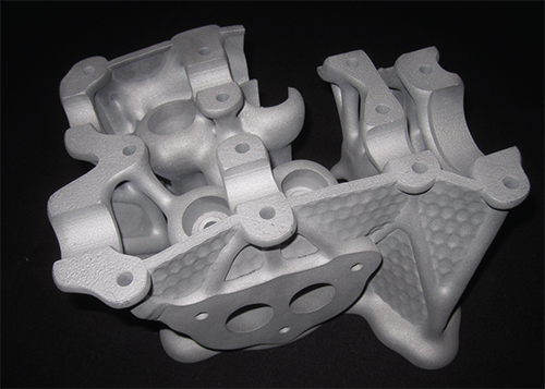
AM also helped FIT optimize the weight of the cylinder head. With the key functional features defined, engineers developed the main body of the head by increasing material thickness around the volumetric shapes. Extra material added strength to the part and served to dampen vibration. The placement of material was determined using topological optimization—the use of mathematics to optimize the strength-to-weight ratio of a design. It results in using the minimum amount of material for given functional parameters. Using topology optimization, the weight of the cylinder head dropped from 11.2 to 4.2 lb.
While the cylinder-head design represents an impressive engineering achievement, this level of design complexity does not come easily or quickly. Part of the success came from the capabilities of the design software used—Selective Space Structures software from netfabb GmBH, used to develop the organic shape and lattice structures.
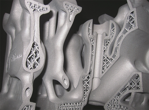 |
Fig. 2—Engine cylinder head with interior lattice framework, courtesy of FIT
|
CFD, topology optimization and lattice-generation software can be expensive and difficult to use. And they require a substantial investment in training, coupled with time-consuming trial and error—often beyond the reach of small companies.
Design Challenges
AM indeed offers interesting design opportunities, but it also introduces unique design challenges. The mathematically optimized shapes generated by the software may not always be feasible to build. For example, it’s important to know the minimum possible wall thickness or the smallest hole that the AM process can produce. Overhanging features also must be supported by extra structures during the AM build process; the supports must later be removed, an important design consideration.
Thermal stresses also present another challenge, particularly during the metal powder-bed fusion process. Here, thermal stresses can lead to warping when the parts are cut away from the built plate. To reduce warping, designers often add anchors to secure the parts and their features to the build plate. However, adding too many anchors creates additional work for their removal; too few anchors will allow curling and warping. The optimum design often requires compromise between reality and the theoretically optimum shapes, although the level of compromise typically is much less than that found with conventional manufacturing processes such as metal casting.
Powder removal represents another critical design consideration. With the cylinder head described above, powder can fill all of the internal cavities and holes. When removing the parts from the build chamber, the technician must remove all of this excess powder. Designers, therefore, should include drain holes and exit paths that will prevent powder from being trapped inside the part. This requires careful consideration of the size and location of the holes and paths, and then adding them to the CAD model. Often, these holes need to be plugged, adding time and cost.
Most designers and engineers have not yet received formal education and training on designing for AM. Consequently, most companies considering AM for production applications are encountering it for the first time. And while some companies have developed tribal knowledge amongst a small group of pioneers within their company, typically these pioneers represent a limited resource. Bottom line: The demand for education and training on designing for AM exceeds the supply.
Training the Aerospace Industry
To meet the need for education in one segment of the aerospace industry, Wohlers Associates has conducted two formal classes on designing for AM, for NASA Marshall Space Flight Center. A four-day class focused on hands-on learning with advanced methods of design, including part consolidation, topology optimization and lattice and mesh structures. The second class, three days, focused mostly on metal AM.
Additive manufacturing offers many opportunities to improve the performance and weight of a design. Using special software tools and techniques, designers can achieve major improvements impossible with conventional manufacturing methods. Since design freedom is much greater with AM than with conventional processes, we believe that AM will find increased use for developing entirely new types of parts and products, including automobile-engine parts, that will be superior to their predecessors in many ways. 3DMP
Technologies:


 Terry Wohlers
 Ian Campbell