Peter Ulintz Peter Ulintz
Technical Director

Material-Flow Analysis in Cup Drawing, Part 1

January 19, 2020
0
Comments


Deep drawing processes involve a complex system of interactive inputs that must be recognized, controlled and monitored during production to ensure proper sheetmetal flow and process stability. Drawing-related problems can prove difficult to solve, especially when material flow is not well understood. This often leads to guess-and-check problem-solving approaches, or reliance upon outdated rules-of-thumb or past experiences. 
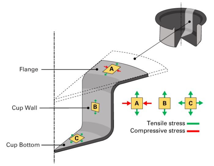
Tensile and compressive-stress combinationsStampers can use simulations to solve deep drawing problems, but many users do not understand how to relate simulation results to corrective measures in the tool. Misinterpretation usually results in a digital form of guess-and-check rather than root-cause analysis.

Sheet Metal Flow

Whether addressing deep drawing problems at the die on the shop floor or on a computer simulation in engineering, solving problems requires a clear understanding of material flow, which involves the application of a force onto a sheet metal blank. That force produces a stress in the sheet, which causes the material to permanently deform, or strain. The resulting strains are both elastic and plastic. Plastic strains produce permanent deformations in the sheet metal, while elastic strains cause the springback encountered when removing the forming loads (die opening).

A fundamental difference exists between force and stress, although many use the two terms interchangeably. Similarly, many people confuse or misuse the terms stress and strain, and material-flow analysis requires a clear understanding of these terms.

Stress, Strain and Volume Constancy

Stress is measured as the force applied to the sheet metal blank divided by the deforming cross-sectional area.
For example, assume 50,000 lbf of force is applied to a 1-sq.-in. area. The applied stress is 50,000 lbf divided by 1 sq. in., or 50,000 lbf/in.2

When that same force is applied across a larger cross-sectional area of 2 sq. in., the applied stress drops (50,000 lbf/2 sq. in. = 25,000 lbf/in.2) but the applied force (50,000 lbf) remains the same.

Reducing the applied force in a deep drawing process will not necessarily improve material flow to solve a splitting problem. However, applying that same force over a greater cross-sectional area often provides the solution. Sometimes applying a greater force (more press tonnage) distributed over an increased cross-sectional area will solve splitting problems. This approach is counterintuitive and often overlooked as a solution, especially when the difference between force and stress is not understood.

Strain is the deformation (or displacement) of the material resulting from applied stress. If a pulling force is applied to a rubber band anchored at one end, the rubber band will stretch. Strain represents the increase in length compared to the original length. 

For example, if a 2-in.-long rubber band is stretched to a length of 2.4 in., the rubber band has increased in length by 20 percent as compared to its original length. We refer to this as 20-percent engineering strain. Here, the strain is elastic, which means that when the load (pulling force) is removed, the rubber band will return—or spring back—to its original length. Many elastomers behave in this manner.

In contrast, suppose a narrow strip of steel is placed in tension and strained by 20 percent. The strip will experience a permanent change in its length, or plastic deformation. When the tensile (pulling) load is removed, the strip retains its longer length, but it also springs back (shortens) slightly. 

The same effect occurs when bending sheet metal at a 90-deg. angle. When the load is removed, the part remains deformed but the 90-deg. angle changes slightly due to the elastic strains in the material relaxing. 

Conversely, compressive stresses would reduce the length of the strip. In the free state, the strip likely would become shorter by buckling. But if a flat plate with springs behind it were used to apply pressure over the strip to prevent buckling, the material would become shorter via an increase in thickness. 

Constancy of volume is another basic characteristic of metal forming where the volume of the sheet must remain constant during deformation. For example, when tension is applied to a narrow strip of sheet metal, the strip lengthens, but it also thins in the stretched area. Thinning allows the total volume of the strip to remain constant even though it has “grown” in length.

In deep drawing, tensile and compressive stresses act together to cause the sheet metal to flow (deform). The magnitude and direction of these stresses determines if the strip thickness will increase, decrease or remain the same after deforming.

Cup Drawing

In cup drawing, tensile- and compressive-stress combinations are induced at various locations, as shown in the accompanying figure, Stresses Found in Cup Drawing. The primary zones of interest: the cup bottom, cup wall and flange.

The punch force acting on the blank causes the material to begin bending over the punch radius and the die entry radius. The stress at bottom of the cup begins to transfer to the cup wall, creating the cup bottom.

Material just above the cup bottom experiences tangential tensile stress and longitudinal tensile stress, while a narrow ring of unsupported metal between the punch-nose radius and the die-entry radius experiences plane-strain conditions. In a plane-strain condition, sheet metal is bent in one direction, with the width direction constrained—in this case by part geometry—and material flow cannot occur sideways. To maintain constancy of volume, the material must thin in this narrow zone. This often leaves a visible mark on the outside cup wall just past the punch-nose radius. This mark is commonly referred to as a neck, shock line or die-impact mark.

The die-impact mark also serves as a demarcation line for metal-flow analysis. Sheet metal above the die-impact mark moving toward cup bottom is subject to biaxial stretching, or stretching in both the X and Y directions. The magnitude of stretching relates to punch geometry. A flat-bottom punch with a relatively small nose radius induces less thinning at the bottom of the cup due to the low stresses placed on the punch face, as compared with the higher stresses (and greater thinning) imparted by a hemispherical punch.

The die-impact zone itself is subject to plane-strain conditions—stretching in one direction only—while the cup wall above the die-impact mark is subject to a combination of strains. The blank is drawn in tension toward the die cavity while the being compressed in the circumferential direction. These specific combinations of tensile and compressive strains are referred to as drawing. 

In Part 2, we’ll tackle analysis of sheet metal flow in the cup wall and flange. MF

Industry-Related Terms: Bending, Blank, Case, Die, Drawing, Flange, Form, Forming, Plastic Deformation, Plate, Thickness, Transfer
View Glossary of Metalforming Terms

Technologies: Tooling

Comments

Must be logged in to post a comment.
There are no comments posted.

Subscribe to the Newsletter

Start receiving newsletters.