Peter Ulintz Peter Ulintz
Technical Director

Redrawing and Ironing Cylindrical Shells, Part 3

February 26, 2020
0
Comments


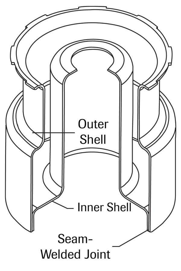
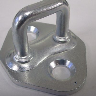
Fig. 1—This two-piece, seam-welded canister represents the original design of an internal component for an air-dryer unit used on a truck braking system.

Part 1 of this series examined the differences between cylindrical redrawing and ironing processes. Part 2 provided guidelines for punch-nose geometry and draw-sleeve design. This month: A practical application for combining drawing and two redrawing operations in a single die process.

Product Design

Manufacturing processes most often are designed based on the product design. Occasionally, a product can be designed or redesigned based on the process.

For example, in 1997 a customer sought to produce an internal component for an air-dryer unit used on a truck braking system. The design comprised two deep-drawn stampings seam-welded together (Fig. 1). Since this component creates two discrete chambers inside of the air dryer, the seam welds could not leak. Such a design requires a significant amount of tooling (two different parts), weld fixturing and 100-percent leak testing of the welds. As a result, an alternative design (Fig. 2) was proposed.

Process Design

The proposed process required a draw, reverse-draw and another reverse-draw (or double-reverse draw) performed in a single die and single press cycle.


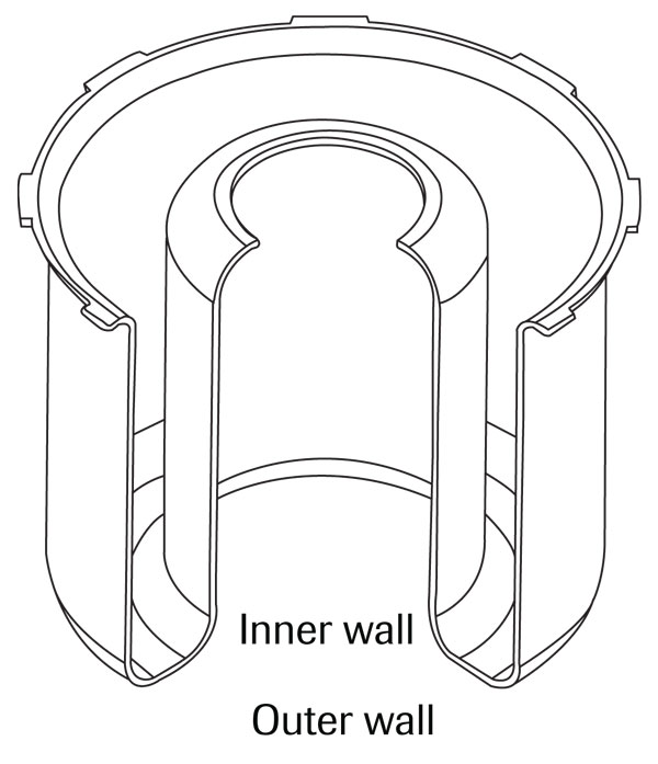
Fig. 2—As the design shown in Fig. 1 would require a significant amount of tooling, weld fixturing and 100-percent leak testing of welds, this one-piece alternate design was proposed.

Providing the needed volume between the inner and outer walls of the chamber required relatively large and unbalanced draw reductions. Specifically, a 1.14-mm-thick blank was reduced by 47 percent in the first draw, 30 percent in the second draw to establish the outer wall (Fig. 2) and 35 percent in the final draw to create the inner wall. The third draw reduction presented the greatest challenge, as that reduction typically would be limited to 25 to 27 percent.

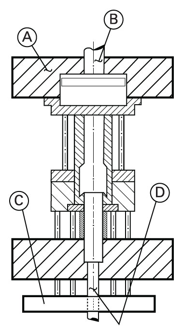
A computer-controlled four-cylinder hydraulic press was selected for this process. The press and tooling (Fig. 3) consisted of four main components: (A) main cylinder to which the outer slide (or ram) is mounted, (B) inner cylinder, (C) bolster plate with a hydraulic cushion and (D) an additional cylinder through the center of the bolster plate.

The press (cylinder) actions are programmable for force, position, speed, time (delay) and direction. A closed servo system controlled the press, allowing programmable press force acting independently of speed and oil temperature. These attributes provide opportunities to control material flow in ways not possible with a traditional hydraulic press.

Tool Geometry


Fig. 3―—A computer-controlled four-cylinder hydraulic press, as diagrammed here, was selected to produce the redesigned part shown in Fig. 2.

To preserve as much formability as possible, large radii that blended completely and smoothly into the die walls were incorporated to reduce high strains caused by bending and unbending. These features were made to print in subsequent restrike operations.

During initial tool tryout, the draw and first reverse-redraw performed as expected but the canister fractured immediately upon start of the second reverse-draw. This was due to highly localized tensile forces acting at the punch-nose radius (Fig. 4a) and the high forces required to cause the shell wall’s edge to flow toward the die cavity.

A hemispherical dome was incorporated into the geometry of the final redraw punch (Fig. 4b) for two reasons: 1) reduce the localized tensile strains that caused breakage during the initial tool tryout and, 2) provide a predetermined amount of biaxial stretching of material into the die cavity to control material flow throughout the second reverse draw.

Computer Assistance

The press was programmed to incorporate a regressive kinematic motion for the redraw die ring, keeping the upper die ring stationary while the ascending lower punch stretches the dome until the material is tangent with points A and B (Fig. 4b). At the instant of tangency, the die ring regresses (raises) at a relative rate while the punch continues its upward travel and draws additional material around the die-entry radius and into the cavity. A tractive force on the die ring still is required at the sheet and radius interface to prevent wrinkling, which makes programming both challenging and critical.

As the process proceeds, the edge of the open end of the shell remains in the same position as at the conclusion of the first reverse-draw step. Material in the wall of the outer shell never moves during the second reverse draw. This reduces the force required to deform the metal and allows a larger diameter reduction. The process does not ‘know’ that material located beyond the die radius even exists. It only experiences, in terms of applied force and friction, the material being ‘freed’ by the regressing die ring.


Fig. 4—Fracturing of material immediately upon the start of a second reverse-draw (a) operation necessitated a change in tool geometry (b).

Though remarkable, the final process was not revolutionary. The draw-reduction ratios, tool geometry and metal flow,―although enhanced by the regressing die ring―follow long established metal forming principles. The application of computer controls provided specific die kinematics and material restraint, making the process possible.

Something to consider: The process described was developed more than 20 yr. ago and continues in production to this day. Over the past two decades, computer controls, hydraulic technology, die steels, tool surface treatment and lubricants all have advanced considerably. What’s possible today is limited only by one’s imagination. MF

The preceding column was adapted from a technical paper written by the author, Tractive Kinematic Regression—A Computer Assisted Deep Drawing Method, and presented at the 2000 ASME International Mechanical Engineering Conference and Expo (MED-Vol.11 p.523-530). 

Industry-Related Terms: Draw, Drawing, Edge, Forming, Hydraulic Press, Plate, Surface, Wrinkling, Center, Die, Bending, Blank
View Glossary of Metalforming Terms

Technologies: Tooling

Comments

Must be logged in to post a comment.
There are no comments posted.

Subscribe to the Newsletter

Start receiving newsletters.