 Here we address three causes of injuries to RW-machine operators:
 To reduce the potential for expulsion, use a proper welding schedule developed specifically for the type of workpiece material. This starts by setting a squeeze time long enough to allow the electrodes to touch and rise to full force before welding current starts to flow. Some RW controls employ a differential pressure transducer system to automatically ensure full force is reached before the start of weld heat.
Next, selection of the proper electrode force, which creates a mechanical barrier around the molten metal to keep the material within the nugget area and eliminate expulsion. It also reduces the electrical resistance between the electrode face where it contacts the outer sheet, reducing surface heating under the electrode and preventing it from reaching the molten state. This results in a visually clean, smooth area for each weld spot.
 However, use of excessive weld force reduces the amount of heat created in the nugget zone and compromises weld strength or, in extreme cases, eliminates fusion. The “RWMA Resistance Welding Manual Edition 4” (available at rwma.org) includes a collection of welding schedules for most metal alloys to provide high-strength welds while eliminating expulsion.
Another cause of expulsion: placing a spot weld too close to the edge of a part. Here, even use of proper electrode force will not prevent molten metal from flying out of the workpiece edge. The RWMA handbook recommends minimum edge distances to minimize expulsion. However, where part design forces a weld location too close to an edge, metal formers can employ a pulsed-current welding schedule to minimize expulsion while maintaining weld strength. For most alloys, divide the weld time recommended in the RWMA handbook by 3 (round up), and install three pulses of this time with two cycles of cool time between pulses. This will minimize expulsion and form a nugget with acceptable penetration. (For an extensive article on electrode force and expulsion, visit www.unitrol-electronics.com. Click on Support, Improving Resistance Welding, and The Effect of Tip Force on Weld Quality and Electrode Life.)
Pinch-Point Injuries
OSHA 1910.255(b) (4), addressing resistance welding, states: “All press welding machine operations, where there is a possibility of the operator's fingers being under the point of operation, shall be effectively guarded by the use of a device such as an electronic eye safety circuit, two hand controls or protection similar to that prescribed for punch press operation.” Unfortunately, many shops operate RW machines without any operator protection.
First, we must understand the magnitude of force between the electrodes. For example, electrodes with a ¼-in.-dia. face and with 600 lb. of electrode force will develop 12,230 psi of pressure, which can cause major crushing damage or possible amputation of an operator’s finger.
Metal formers can select from several devices available to help prevent pinch-point injuries.
 Two-hand anti-tiedown initiation finds use when part and fixture designs allow for welding without the operator holding the part (Fig. 2). These devices will prevent the operator’s fingers from entering the pinch-point zone during welding. The RW machine’s initiation buttons should be far enough away from the electrodes to prevent any part of the hand from entering the weld zone while pushing the initiation buttons. The welding machine must only operate when both switches are pushed within less than 1 sec. of each other. If the switch on either side becomes permanently closed, closing of the second switch must not cause the machine to operate (anti-tiedown function). If the space between the electrodes exceeds ¼ in., the control should be set so that releasing either initiation switch before the electrodes close causes the electrodes to immediately retract. One downside of this method: The parts must be supported in fixtures or otherwise held in place, as operators are using their hands to depress the initiation buttons.
Light curtains typically prove impractical during hand-fed RW operations, as the operator’s hands often will enter the welding-electrode zone. Also, light curtains usually cannot handle parts with flanges in the same area as the operator’s hands. However, metal formers can employ light curtains effectively for automatic and semiautomatic RW machines provided that the curtains prevent mechanical movement when the light curtain is broken. Here, once the welding sequence commences, breaking of the light curtain should automatically cause any moving components to retract to a safe position, and then require re-initiation of the machine once the beam has been cleared to restart the weld sequence.
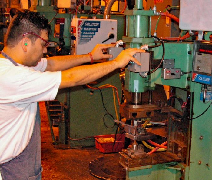
 Continuity monitoring (such as with the Unitrol Soft Touch system) measures electrical continuity between the electrodes to determine if the electrodes are touching the workpieces. In operation, the electrodes close under low force (less than 50 lb.) via use of a precision pneumatic-valve system. Should the system detect continuity within a preset time limit, the electrodes are brought to full welding force. However, if continuity does not occur in time, the electrodes automatically retract and will not move together until the operator has released and then closed the initiation switch. These setups do not have any operator-set components; do not require any adjustment when developing new setups; cannot be overridden; and always remain in place when the RW machine is under power. And, because this is a fully passive process, it can be used as the primary pinch-point safety system. With a continuity detection system installed (Fig. 3), the operator can use a foot pedal to safely initiate each weld and leave both hands free to hold the workpiece. In addition, continuity detection protects the operator even during installation and adjustment of electrodes by use of a tip-dress safety system.
Ring guards typically employ a rod with a horizontal ring installed at one end that encircles the moving electrode. Operators must adjust a limit switch every time they create a new setup on the RW machine so that the electrodes can close only after the rod travels to a position less than ¼ in. from the workpiece. When initiating the machine, the rod lowers before the electrode begins to move. If the limit switch closes within a set time, the rod retracts while allowing the electrode to travel forward to make the weld.
Ring guards only work when the parts being welded are flat in the weld zone. More importantly, since the level of safety depends on the precise adjustment of the limit switch during each setup, use of ring guards is non-passive and, therefore, should never be used as the primary pinch-point safety system.
 Mechanical barrier guards find use for safeguarding automatic or semiautomatic RW machines. Take care to install them so that they automatically close at the start of each welding sequence. The moving barrier contains an interlocking limit switch to prevent electrode movement if the barrier is not fully closed. Design and install the mechanical barrier so that it prevents the operator from reaching into the electrode area when in place, and that the closing force of the barrier will not cause injury to the operator should the moving barrier make contact with any part of the operator’s body. Lastly, metal formers can employ these barriers only on parts that must not be held during welding and are small enough to be surrounded by the barrier guard.
Complete cage guarding gets the call when safeguarding automated and robotic RW cells. Install a cage around the entire cell that prevents machine movement within the cell when an entry door is open. If an entry door opens during a welding sequence, all movement must stop. Once the door closes, movement can start only when the operator has activated a switch on the outside of the cage.
Electrical Shock
By design, an RW machine uses low voltage at the electrodes to produce an intrinsically safe process. However, an incorrectly grounded machine can pose potentially serious shock danger to the operator. Here, a potentially fatal shock can occur if the primary winding of the welding transformer shorts to the transformer secondary winding, or if a line-voltage connection in the transformer housing comes loose and shorts to the machine body.
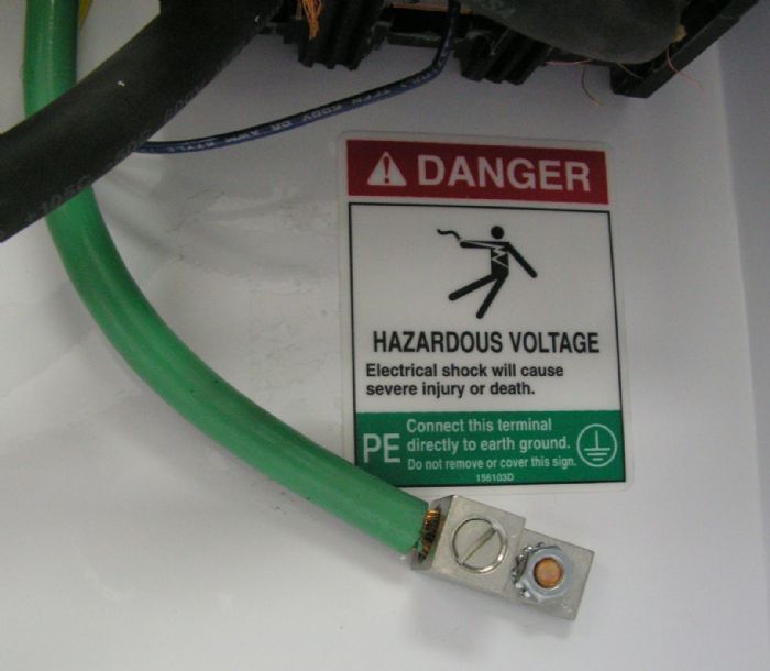
With a properly grounded machine, the line voltage will find a good path to ground and clear the control’s circuit breaker, line fuses or main power circuit breaker. Proper grounding depends on the quality of the incoming ground wire to the machine. Do not ground an RW machine using the conduit or BX cable. The separate ground wire should enter the welding-control enclosure and connect to a properly bonded ground stud. The wire, sized large enough to handle at least 50 percent of the current capacity of the incoming main power, should connect on one end to earth ground (Fig. 4).
OSHA standard 1910.255(b) (9) reads: “Where technically practical, the secondary of all welding transformers used in multispot, projection and seam welding machines shall be grounded. This may be done by permanently grounding one side of the welding secondary current circuit. Where not technically practical, a center tapped grounding reactor connected across the secondary (is acceptable).”
Floor- or bench-mounted press and rocker-arm RW machines typically are manufactured with the stationary arm bolted to the transformer secondary pad and connected to the machine frame. Grounding the machine frame completes the path from welder secondary to ground; the movable machine arm is not grounded.
Machines that use a permanently mounted transformer connected to a portable welding gun by a long kickless cable require a ground strap to connect either side of the transformer secondary to the transformer frame. With the transformer frame properly connected to a ground wire, the path from the portable welding gun to ground is fully established.
Proper Grounding of Portable and Robotic Transguns
With portable transguns—one package combining a welding transformer and welder arms, typically suspended by a counterbalanced mount and positioned by an operator—a flexible cable enters into the transformer carrying line voltage from the machine control. Because this portable device cannot be hard-connected to a suitable ground, the ground wire enters the machine in the same flexible cable that contains the line-voltage wires. While many older transguns were supplied simply with a double-pole contactor between the control and the transgun, this form of protection does not suffice for personnel protection and can expose the operator to potentially fatal electrical shock even when the machine is under power but not being operated.
RWMA Bulletin #5 (Resistance Welding Control Standards), section 5-015.68.04, covers the special requirements for grounding of portable transguns. Because the transgun is not hard-grounded, operator safety depends on the presence of a reliable ground path. However, as the ground path comes from a long flexible wire, additional requirements apply for monitoring ground-wire integrity and ground-fault leakage current.
- Grounding integrity: RWMA requires that “the welding gun transformer case and secondary shell be grounded and protected by fail safe circuitry designed to immediately disconnect line voltage from the transgun via a circuit breaker with under voltage trip. The combined clearing time shall not exceed 60 msec. A sensed value of grounding conductor resistance in excess of 1Ω by the ground integrity monitor would be considered an inadequate ground.”
- Ground-fault current relay: If the transformer primary shorts to the secondary, line voltage will be present on the transgun case. As the operator maneuvers the transgun while holding parts of the machine case, the voltage will find a path through the operator and to ground. This leakage through the operator reduces current returning to the control and can be measured by a ground-fault relay.
The RWMA standard continues: “A sensitive, failsafe ground-fault relay with a maximum trip point of 15 mA must be used to provide protection against ground-fault leakage currents. The ground-fault relay must immediately disconnect line voltage from the portable transgun via a circuit breaker with an under-voltage trip. The combined clearing time shall not exceed 60 msec.”
When purchasing a new transgun for hand-held application, verify that that the welding control contains systems to match the above requirements. If operating an existing hand-held transgun, ensure that the welding control includes this full protection.
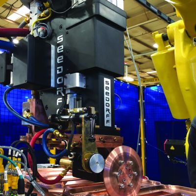
When using robotic transguns, because the frame-grounding path to a robotically manipulated transgun runs through hinge points, grounding requires use of a separate ground wire such as that for the portable transgun. Because the operator may potentially touch the frame of a transgun, use the same type of grounding integrity and ground-fault current relay applied to portable transguns.
Multiple Transformers
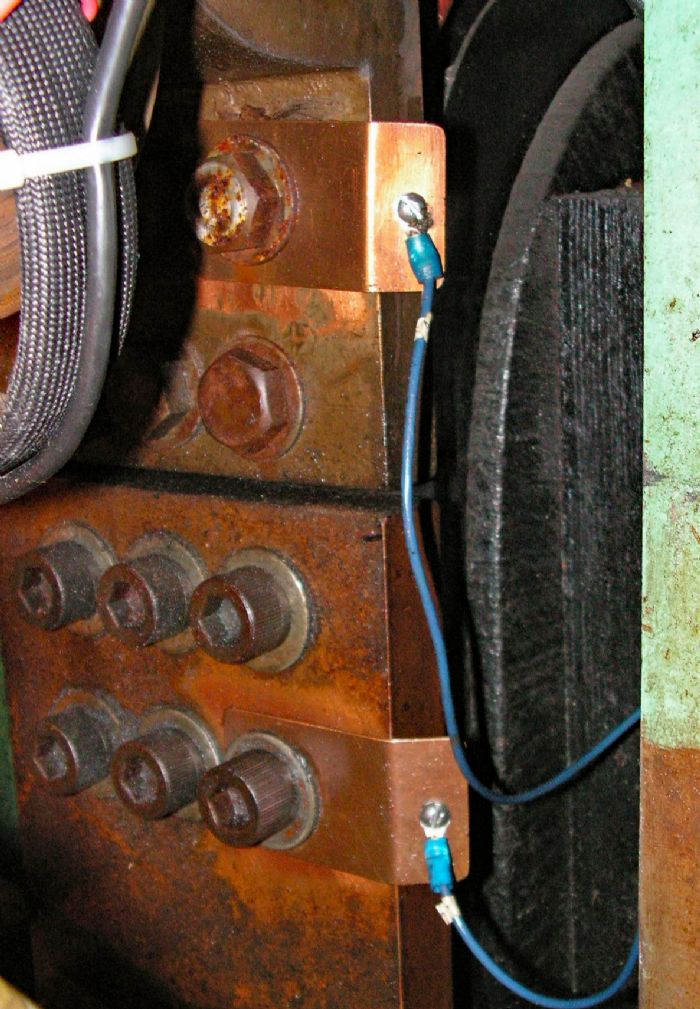
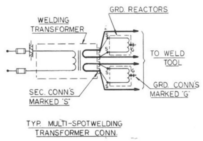
RW machines that employ multiple transformers on the same structure require special grounding (Fig. 5). Connecting one side of the machine’s secondary on multiple transformers to the common ground causes ground paths to run through the workpiece and fixture. These ground paths easily can weld or tack the parts to the fixture. In addition, electrical paths may run back through the workpiece to other grounded electrodes, causing arcing throughout. For this type of application, metal formers should install a grounding reactor on the transformer secondary in place of a hard-wire ground.
These devices contain an internal coil connected across each weld-transformer secondary with a third wire from the center tap on the coil connected to ground. The coil has high impedance when voltage applied across it is less than 24 V. However, should the transformer secondary become connected to line voltage, due to a transformer internal short, the coil saturates and becomes a very-low-impedance device. This drains the line voltage through the ground wire, producing excessively high current that should trip the control’s circuit breaker or blow the fuses. If the transformer has two secondary circuits, be sure to install one grounding reactor on each circuit.
Finally, with permanently mounted transguns, complete the ground path by connecting either side of the machine transformer secondary to the transformer frame. When using multiple transguns in a system, or where arcing to the fixture may occur, employ a grounding reactor for each welding transformer secondary in place of a hard-wire ground connection. MF
View Glossary of Metalforming Terms
See also: Unitrol Electronics Inc
Technologies: Welding and Joining