
 “We’re seeing many fab shops performing a lot of job changeovers, which makes accuracy very important because they are cutting fewer blanks—producing in smaller batches and trying to achieve a perfect first part every time,” says Chris Wargo, standalone press brake product manager for Trumpf.
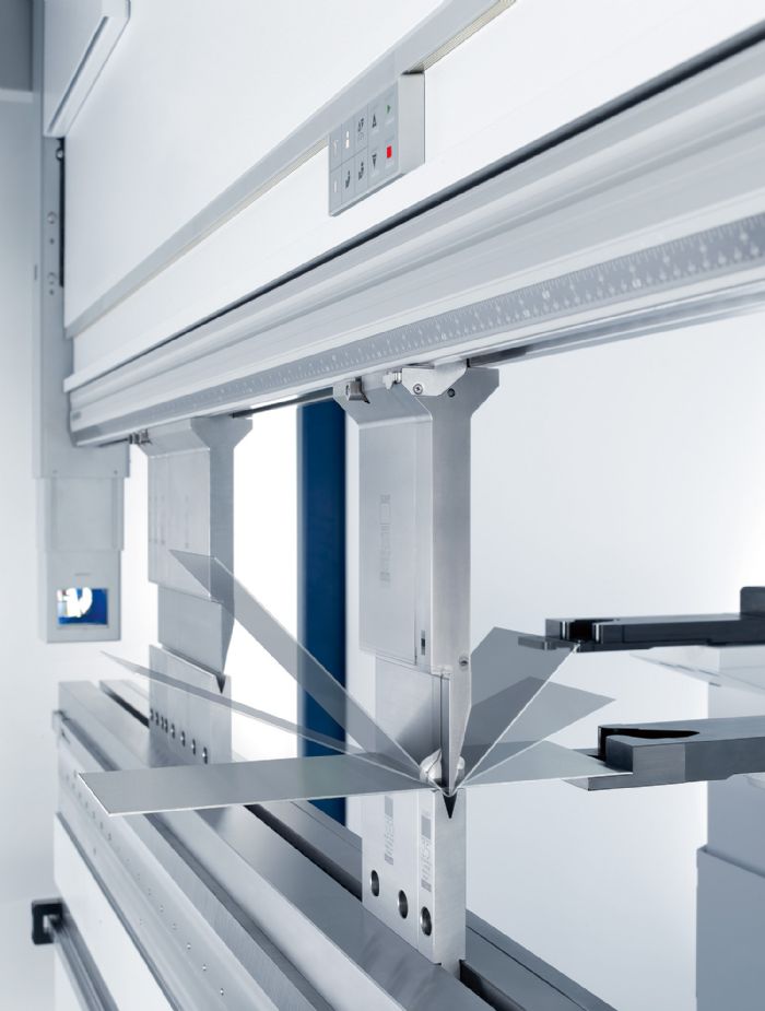 Trumpf also recently has added ACB Laser, a module located on the front of the press brake that slides back and forth automatically and uses an optical sensor—the laser—for bend-angle measuring. Users can program the ACB Laser to measure the same spots on the front and rear of the part or other locations depending on whether or not the part has holes or other features that prevent accurate measurement.
“A newer feature, ACB can measure three points on a part,” he says. “Typically, if bending the full length of a longer part, the left side rests under cylinder one, the right side under cylinder two, and then the center of the part in the center of the machine. All three positions can react differently, and ACB measures all three to provide real-time angle adjustment all the way across.”
Even with all of this real-time measuring, adjusting and bending, ACB reportedly adds only 1 sec. or less to the process.
Other features incorporated in Trumpf press brakes to aid in accurate and productive bending include the ability for the machine to learn from bends in a particular grain direction and apply that knowledge to future bends automatically, eliminating some scanning from the process. Another, included in the ACB technology: monitoring to ensure proper part placement and tilt angles in the machine, as these variables affect bend accuracy. Here the machine indicates improper positioning and won’t bend until it indicates that proper positioning has been reached.
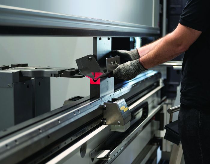
Automatic tool loading/unloading via ToolMaster and automated bending via BendMaster play roles in accurate press brake bending, offers Wargo. ToolMaster ensures quick placement and positioning of the correct tools for a bend sequence. The robot-driven Bendmaster delivers automatic bending and folding, encompassing software as well as material flow and gripper technology to process small and large parts.
This automation technology assists in workforce recruitment, development and retention, according to Wargo.
“Running robotic press brakes is much more attractive than just loading material into a press brake,” he says. “Besides providing quick, accurate, automated processing, technology such as BendMaster adds ‘coolness’ to the job.”
Accuracy Via Machine-Construction Evolution and Measurement Tech.
 Amada has evolved its press brake equipment to enable precision bending by addressing crowning and bend-angle adjustment, reports Scott Ottens, bending division manager. He provides an overview of that evolution, noting that a lack of skilled labor drives such innovation.
Perhaps three decades ago, press brakes might have cylinders located outboard (outside of the forming area), leading to crowning issues—tighter bending toward the outside but some give in the middle. The solution: Up-acting brakes that allow for main-cylinder placement toward the middle, with lighter cylinders located outboard.
“Back then, everyone seemed to bend in the center of the press brake,” Ottens says. “The downside: Tooling advanced, enabling more complex parts with bending all across the bed, providing tighter bending in the middle but less tight toward the outside of the bed.”
The next iteration for Amada addressed this with a down-acting press brake featuring increased design attention paid to the lower beam.
“We’ve designed and built a lower beam in a couple different ways,” Ottens says. “One way, still used on our HRB-series press brakes, via a slotted crown bed, allows the lower beam to match the deflection of the upper beam, providing natural crowning.”
To provide accurate bend angles and angle adjustment, Ottens cites a couple of different Amada press brake features. One: a cam driven by a servo motor that enables adjustment for deflection compensation, available on the firm’s HRB-series press brakes.
“As a user perhaps moves from stainless steel to cold-rolled steel to aluminum,” he explains, “each of these materials deflects differently. Via automatic calculation, the cam mechanism compensates for that deflection. Now, it’s not dynamic adjustment—the cam must move into position prior to the bend.”
The company’s HG-series servohydraulic press brakes dispenses with the slotted crown bed, using two or three hydraulic crowning cylinders on the lower beam to control crowning dynamically, based on material and part information—no need to be set prior to the bend.
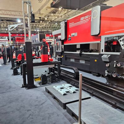
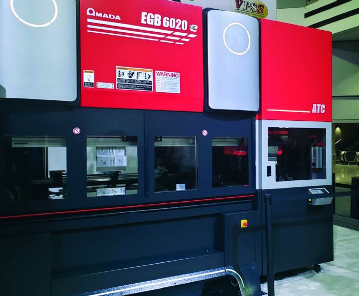
Amada’s recently introduced EGB line of all-electric press brakes—to 130-ton capacity—does not use hydraulic crowning, instead employing a servo-driven cam “plugged in at multiple points across the bed, enabling complete control across the bed,” Ottens explains, “whether off-center bending or just trying to compensate for a center-bending crowning issue.”
For bend-angle adjustment, Ottens describes a few types of technology used in Amada press brakes. The probe-style Bend Indicator (BI) Slide employs sensors that measure three points across the bed and, considering material thickness, grain direction and springback, adjusts bend angle automatically on the fly.
“It provides a guaranteed good angle right out of the box,” Ottens says. “Otherwise, the operator would have to make a bend, measure the angle and then physically make corrections in the control and perhaps re-hit that part. Re-hitting is not a perfect scenario. Where a fabricator may have stainless steel needing some bending with the grain and additional bending against (grain direction can throw off bend angles), deploying the BI slide on every bend guarantees a good angle.”
This type of adjustment can add time to bends, so it serves best in high-mix, low-volume applications.
Another Amada technology, laser-based, lends itself to larger V bends and thicker materials, according to Ottens, as a laser requires a bit more material hanging out of the bed for it to scan and determine the bend angle.
A third type of technology for bend-angle adjustment, what Amada refers to as TDS (Thickness Detection System), reads the variance in material thicknesses and compensates ram-depth position automatically (controlling the D axis) for stable and correct bending.
“Primarily software-driven, TDS does not determine the initial bend angle—the operator still must correct to a good angle—but it does assist when encountering trouble during processing due to thickness variation,” Ottens explains. “In practice, an operator brings the ram down to the pinch point or just below, and the machine takes a very accurate pressure reading. TDS reads material-thickness variation based on the pressure readings and rapidly compensates accordingly. This pays off in achieving consistent bend angles on longer runs.”
Reigning In Variables Key to Bend-Angle Accuracy
 Modern press brakes are designed to ensure bending accuracy, explains Steven Lucas, LVD Co. press brake product manager. He cites features such as servo-controlled hydraulic components to provide energy efficiency and speed control; bed-referenced linear encoders that offer precise control and repeatability of the upper beam position; and backgauges that maintain correct positioning of the workpiece in the machine to reduce overall cycle time and increase productivity. Optional features, he notes, such as CNC sheet supports, bend-angle-measurement systems, CNC crowning and multi-axis backgauges also enhance bend-angle repeatability and quality.
Such an arsenal is required as variables inherent to bending impact the accuracy of the bend angle.
“Deflection of the bed and ram under bending load is inherent to the process regardless of the press brake’s size or tonnage,” Lucas says. “Such deflection can cause an inconsistent bend angle along the part length, varying from the center to the ends. This distortion typically can be compensated for automatically with a single symmetrical, CNC crowning bed (V axis), a built-in feature of many press brakes.
“LVD, in 1993,” continues Lucas, “introduced a mechanical system with a sensor for angle measurement and correction specifically designed for press brakes. Today, many press brakes, regardless of tonnage, are equipped with an adaptive bending system. An in-process angle-monitoring system adapts the ram position in real time to achieve an accurate bend. This eliminates manual test bending and corrections, thus reducing scrap and minimizing operator involvement. A true real-time angle-measurement system provides feedback to the machine control for positioning of the ram to produce an accurate bend without secondary compensation, and without a significant increase in cycle time.”
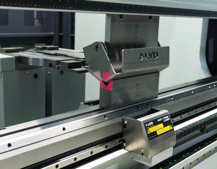
LVD also offers its Easy-Form Laser technology, which brings intelligence to the bending process, automatically compensating for variables such as sheet thickness and grain direction that impact the accuracy of the finished angle, according to Lucas.
“Using Easy-Form Laser,” he says, “sheet thickness or strain hardening of the material no longer influence the bend angle obtained. As a result, the technology provides accuracy and bend-angle tolerance to ±0.2 deg., guaranteeing the desired angle from the first bending operation.”
This angle-measuring technology consists of two laser scanners located on the front and back of the table, and is unique, according to Lucas, in that it uses a V-die reference instead of sheet reference. Easy-Form Laser measures as many as 100 samples/sec. between the die and the sheet. As the bending sequence of the press brake is initiated, digital information is conveyed in real time to the CNC control unit, which processes the information and immediately adjusts the position of the ram/punch to achieve the correct angle without interrupting the bending process or losing production time.
Unlike some adaptive forming systems, Easy-Form Laser does not measure springback during forming, according to Lucas, “as this a slow, challenging and ineffective method. Instead, LVD manages springback values using an intelligent springback database.”
Most recently, LVD has offered its Synchro-Form next-generation adaptive-bending technology for XXL profiles, available in configurations to 3000-ton capacities and in lengths to 46 ft. The technology was designed specifically to address the need of bending boom profiles or large-radius parts for industries such as aerospace, shipbuilding and yellow goods.
“Synchro-Form is changing the process of bending large-profile parts, which chiefly has been a manual, time-consuming operation,” Lucas says. “This advanced technology can improve the productivity of large profile bending by 50 percent or more, depending on the part profile.”
In practice, Synchro-Form automatically positions the part and performs the bend cycle, then measures and compensates automatically in process for accumulated error with no operator intervention needed.
“Variations are not accumulated but rather compensated with each bend,” says Lucas. “Even after multiple consecutive bends, the desired profile is achieved. Offline-programming software programs the parts, eliminating manual programming at the machine.
“This technology,” he continues, “ultimately reduces the direct cost of the large-profile part by reducing manual operations; increases throughput by automating the bending process and ensuring part accuracy; and makes for a safer production environment.”
Electric Drives, Measurement Technology Deliver Precision
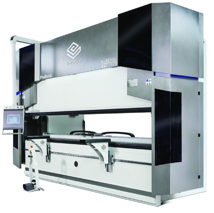 BLM Group focuses on electric solely as the power system for its press brakes, which provides greater accuracy and repeatability than a bread-and-butter hydraulic system. That’s according to Tim Place, BLM Group business development manager, and Robert Jackson, BLM Group application specialist, who note that an electric motor controlling motion offers a fine resolution and much greater precision. For its part, BLM Group uses its own direct-drive torque motor technology that combines with other machine design and construction features to deliver rigidness and stability, minus fluid and mechanical-linkage variables present in nonelectric drives, for accurate, repeatable bending.
Also designed as standard into BLM Group’s press brakes, according to Place, is an operating database that, if a user chooses, tracks every adjustment made by an operator and can use that to learn the springback of a given material to remove material variables. Each operator adjustment to the bend angle helps fine-tune the database’s knowledge, thus aiding future bends of that same material to achieve the needed angle.
Additionally, offline-programming software properly set up with defaults and tooling accurately predicts a flat pattern, which press brake operators historically, and still today, can struggle with, according to Place.
“Zeroing in on a flat pattern as the software learns is one more tool that allows a better probability of success right out of the gate with an operator who doesn’t have 20 yr. of bending experience,” he says. “The software can take a lot of functions out of an operator’s hands, such as measuring and deciding if parts can be produced with particular blanks,. The knowledge base is rare these days with less-experienced operators, so such assistance really helps.”
Even when programming and running new, unrelated parts, offers Jackson, “the database will extrapolate related data points from previously stored parts to provide correction from the start. It’s a nice feature for newer operators that lack a fundamental understanding of the material. They’re not starting from zero. As the database builds, it will start anticipating the needs ahead of the operator—a nice function that almost makes this press brake a smart machine.”
Specifically, to enable active monitoring for bend-angle accuracy, BLM Group provides a few tools depending on machine size. All machines employ Lazer Safe optical safety protection for tool guarding, with machines under 10 ft. of bed length offering Lazer Safe Iris Plus, which features active angle monitoring. This occurs through real-time images taken of a part during bending—as many as 100/sec. as Jackson explains. An Iris Plus feature, Active Angle Control is designed for single parts or small-batch production. During operation, the bend is briefly paused prior to reaching the programmed angle while real-time images are processed to calculate the material springback. The bend then resumes with the springback calculation used to control ram depth automatically. After decompression, the final angle is confirmed automatically before proceeding to the next bend.
Another Iris Plus feature, Dynamic Angle Control, is ideal for high-speed processing of volume production parts. During forming of the first part, Active Angle Control automatically calculates the springback of each individual bend in the part. After springback calculations for the first part, Dynamic Angle Control activates and uses real-time angle data and springback calculation to control automatically the bending depth, with the final angle confirmed after decompression before proceeding to the next bend.
For press brakes with beds longer than 10 ft., BLM Group employs a Data M LaserCheck optical angle-measurement system—more accurate at longer lengths, according to Place and Jackson.
“Both systems, depending on their use, are extremely accurate,” Jackson says, “because they both measure multiple points, not a single point.”
Full-on 100-percent measurement to ensure tight tolerances does add a little extra time on a job run, so, as Jackson explains, that can be addressed in the quoting stage.
“If a customer has a job demanding ±0.5-deg. accuracy and no allowance for out of tolerance, a fabricator can quote to assume extra time as it will require 100-percent measurement and inspection,” he says. “Conversely, if required tolerances amount to ±1.0 deg., the machine can meet such tolerances without using Iris Plus.”
Place concurs, noting that as jobs build, the machine-control database will recognize the same materials with the same grain direction, and the press brake can run with Dynamic Angle Control from the first part.
“Still,” Place says, “we recommend that users take measurement on a first part to account for variables.”
Finally, Place and Jackson note the importance of tooling in achieving part accuracy, regardless of press brake manufacturer.
“Precision-ground, well-maintained tools help to remove a variable,” Place says. “Good tools make a difference in any press brake.”
Ease of Operation, Automated Adjustment Combat Skilled-Labor Shortage
 Given the dearth of available skilled labor, the onus falls onto machine manufacturers to deliver rigid, dependable equipment with technology that eases processes for users and brings them to speed quickly, while delivering accurate product. This idea holds quite true in the press brake world, offers Chad Alan, product manager-bending/automation for Bystronic Inc.
“Whether it’s a large OEM with a specific process in place, or a job shop that gets a diverse product mix coming through the door, without experienced operators used to seeing different characteristics, fabricators are placed in bad positions,” he says. “It’s difficult to find experienced people off the street.”
“On top of that,” Alan continues, “fabricators must deal with diverse materials—grain direction, tensile strength or even the mill spec from the material supplier being a bit off from the order. My favorite example: I’ve never seen 16 gauge come in at 0.068 or 0.060 in. It’s always 0.063 or 0.057 in.”
That’s why, as Alan explains, Bystronic focuses on sturdy machine construction and technology to provide ease of use, accuracy and repeatability, and training to make sure that owners and operators employ this technology to the fullest. He points to Bystronic’s algorithm for processing real-time data as the backbone of press brake accuracy.
“CNC control is not new,” Alan says, “but ByVision Bending—Bystronic’s human-machine-interface (HMI) software—allows for rapid data translation into numerical code to keep bend angles true. Whether through top-of-the-line hydraulic valves or high-end PLCs for rapid network communication, the press brake constantly reads and reacts to the information provided by the software’s dynamic pressure-regulation system. This closed-loop system measures 200 times/sec. to keep information current.”
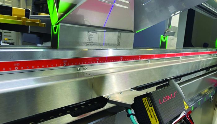
For real-time bend-angle measurement and adjustment, Bystronic offers LAMS (Laser Angle Measurement System), a photolaser device that travels on the front and rear of the table. Using a machine’s HMI, an operator enables LAMS, and holds and drags the camera system along a track to one work-material position best suited for measurement.
“Often,” relates Alan, “we’re asked, ‘what if an operator wants to measure in three different locations?’ During commissioning of the press brake (which features thicker-steel construction and precise component fitup that assists in proper data collected), we ensure the accuracy not only of the upper ram but of the bottom table—deflection is monitored and the machine is tuned. Operators do not need to shim under the dies or on top of the work materials. With a properly tuned machine, there’s no need to measure a part in multiple locations—one angle-measurement reading ensures correctness along the whole piece.”
Though positioning proves quick for an operator to enter, it also can be accomplished via offline programming where a measurement position is written into Bystronic’s BySoft bending software and exported to the press brake.
When in position, LAMS emits a blue laser to register the angle of the material in the V die. Why a blue laser?
“We’ve switched to a blue laser in our latest generations of LAMS from red in previous generations,” Alan says. “Red does not work as well with reflective material and ambient light, which makes laser processing more difficult.”
Upon laser measurement of work material coming out of the die and the reference point of the V-die shoulder, the software recalculates the needed Y-axis ram position to achieve the required bend angle.
LAMS allows for a real-time angle measurement and adjustment should the predetermined ram position fail to yield the desired angle, according to Alan.
“It is a very reliable tool for forming the correct angle without the need for bending multiple pieces during setup,” he says, “beneficial for fabricators seeking to minimize scrap or to achieve tight tolerances for optimizing downstream processes.”
Though developed for ease of use, Bystronic includes extensive training to ensure proper operation of LAMS and other features, according to Alan, which assists in bringing less-experienced operators up to speed.
“During included training, operators not only learn about a machine’s layout and control, but also bend theory,” he says.
Bringing training back to the design process, Alan adds, “can result in good production parts without rework that wastes time and material, and which may compromise the structural integrity of parts.”
Building Bend-Angle Accuracy into Press Brake Design and Control
 Cincinnati Inc. has been producing press brakes for more
than a century. Over that time, the company has learned that building accuracy
into the press brake involves three keys areas, according to Todd Kirchoff, product
manager.
Cincinnati Inc. has been producing press brakes for more
than a century. Over that time, the company has learned that building accuracy
into the press brake involves three keys areas, according to Todd Kirchoff, product
manager.
“Producing accurate bend angles on a press brake requires close attention to machine design and condition, operator ability, and material specifications,” he says. “During the development process, Cincinnati engineering, applications, safety and service departments collaborate to optimize these areas.”
Kirchoff then goes on to describe how Cincinnati press brakes achieve needed accuracy.
Machine Design. Ensuring angle accuracy starts with building stability into the press brake frame which comprises the bed, ram and side housings. The frame must have minimal deflection and twist under load, for accurate results. It’s also critical to maintain precise control of the ram position throughout the stroke. Fast-response hydraulics and precision linear encoders continuously monitor the distance between the bed and ram, then feed this distance position to the control. Precise ram control is especially essential to achieve optimal results while air bending—today’s most common forming method.
Operator Ability. A well-designed control can improve an operator’s abilities—not only so that an operator can set up the machine quickly, but also to prevent programming errors that could damage or knock the machine out of alignment permanently. A press brake that is not in optimal condition cannot produce optimal results.
For example, a well-designed control can ease how an operator enters a ram reversal value. A tooling library that contains the tool’s critical dimensions allows the operator to simply enter the desired bend angle. The control does the rest by automatically calculating the exact ram reversal position to achieve the desired angle without die crashes.
Material Specifications. Finally, most operators would notice the difference between two different gauge thicknesses fairly readily. But it would be expecting too much of an operator to feel gauge differences of only a few thousandths of an inch. Because thickness variations always exist from piece to piece, a few thousandths of an inch can cause bend angles to drift out of tolerance. For example, in a 16-gauge material, a few thousandths of an inch can cause more than a full degree of bend-angle variation.
Cincinnati’s Dynamic Thickness Compensation system detects these small variations and adjusts the ram reversal position automatically to hold the bend angles in tolerance.
Cincinnati’s latest press brake model, the XForm, provides advancements in cycle speed and energy savings, and real-time feedback. However, unchanged is the rigid frame design and simplified program controls that are key to achieving accurate bend angles that press brake users need. MF
View Glossary of Metalforming Terms
See also: LVD North America (Strippit Inc), TRUMPF Inc., Cincinnati Inc., Amada North America, Inc, Bystronic Inc.
Technologies: Bending