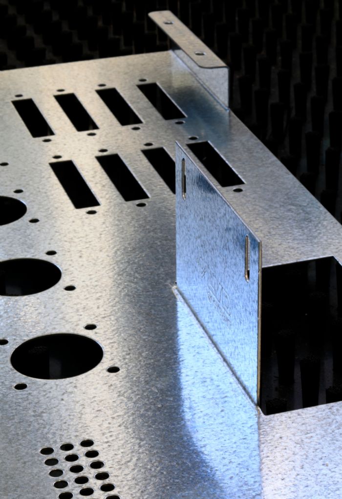
 The modern CNC punch press is capable of so much more than machines designed just 10 years ago. It can punch, form, mark and tap. In fact, more fabricators perform forming operations in their punch presses than ever before, whether to add value to a part or to eliminate secondary processing. Forming operations include countersinks, tabs, knockouts, louvers and even continuous embosses.
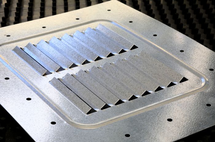 Everything from the size of the micro-joints, sequencing of tools, direction of the tool paths, and when and where to place parts with forms will impact sheet stability during production and, consequently, part quality, process reliability and productivity.
 Micro-joints seem simple enough, as most programming software includes a default for either a material-thickness percentage or a set value. However, the size of the micro-joints must change depending on the material used—a variable for which programming software does not compensate. What works for mild steel differs from that used for aluminum or higher-tensile materials such as stainless steel. The material type and thickness, and the number of joints, all factor into determining the proper size of a micro-joint. For instance, thin material will require thinner micro-joints. If you place a thick or large micro-joint on thin material, it will take more effort to release the parts from the skeleton. The most efficient micro-joint will keep a strong enough bond to the sheet to keep the part stable during processing, but then break cleanly with a shake of the sheet without requiring a secondary operation for part cleanup.
If the micro-joint is not properly programmed and the interconnecting tabs do not remain intact or do not allow for simple part separation, ramifications could include having to stop the machine to remove loose parts from the table, or using a screwdriver or other tool to manually break out the parts. The latter could deform the parts and potentially add cleanup in the form of a secondary operation.
What if you’re using a four-way radius tool on the corners of a part and need micro-joints along the length of its sides? Placing a straight micro-joint on the part will require a secondary operation to either file or grind off the nub. A better solution: Use a micro-joint tool or bowtie tool. Used properly, this will provide a breakoff just underneath the surface of the part.
2. Internal hits
When programming internal hits on parts, programmers should move from the smallest hole to the largest. This practice helps to avoid large openings in the sheet having to move over the lower turret. If the opening catches on a form die, such as a louver or an emboss, the result most likely will be a sheet of wasted material.
3. Tool load
 When outlining the turret tool load, the programmer must understand tool usage and consider tool positioning. Avoid placing a form tool next to a standard punching tool, as this might damage the form. And, placing a form tool next to a parting tool might cause sheet deformation. Punch standard holes first whenever possible.
Forms tools can present programming challenges. Form dies usually are taller—sometimes significantly taller—than standard cutting dies simply due to the action they must perform. This is especially true of form-up tools such as lances, louvers and hinges. The die height matches that of the form to be produced. Form dies sit above the die shoe, while standard cutting tools sit more or less flush with the die shoe. Because of their height, form tools have a greater risk of colliding with the workpiece material, or causing other issues such as part distortion or breaking micro-joints. Poorly planning the positioning of higher form dies undoubtedly will result in negative consequences.
4. Wheel tools
Wheel tools have advanced greatly since their introduction, and find frequent use for cutting, forming, punching and producing offsets They do, however, require special consideration. When using wheel tools, programmers must consider part placement on the sheet. For example, when using a wheel tool on thin-gauge material, do not position parts near the edge of the sheet opposite of the work clamps, as the material lacks sufficient strength to prevent buckling. Instead, place the part closer to the work clamps or even in the middle of the sheet to prevent sheet distortion and improve results.
Also, keep in mind the direction in which the wheel tool will operate. If the tool moves toward the work clamps, the risk of sheet buckling increases. Instead, have the sheet move away from the clamps. Horizontal movement is fine, but steer clear of the far edge of the sheet. Most issues with the programming of wheel tools relate to directional movements.
As for work clamps, when punching close to the edge of the sheet, ensure that the clamps won’t collide with a form die.
5. Tool paths
Tools paths also must be optimized. Most offline-programming software excels at tool-path optimization, but when including special tools in the mix, programmers should double-check the auto-generated paths. For instance, programmers should check to ensure that a parting tool will not collide with a tall form. Or, they might look to add an evasive move around a work clamp—most machines automatically slow down when the work clamps move through the turret; adding an evasive move will eliminate this slowdown.
Programmers also should ensure that the punching operation progresses in smooth, streamlined movements. Jumping randomly around the sheet puts more wear and tear on the equipment, and usually results in reduced productivity. Optimize machine movement in the X axis as much possible, but also try to reduce unnecessary movements overall. Avoid making zigzag movements or an evasive move around a countersink tool that may be mistaken for a form-up tool. When it comes to parting-out the nest, the smoother the table movement the higher the likelihood of holding parts in the nest with a minimal number of micro-joints.
6. Work clamps
Finally, programmers will want to examine the placement of the work clamps along the X axis, positioning the clamps to achieve the best possible sheet utilization, avoiding sheet repositioning and having the least amount of clamp movements. The goal is to obtain the best processing times with the highest sheet utilization while keeping the worksheet stable.
Practice Teamwork
Optimizing productivity from each punch press requires the skill and knowledge of the programmer and machine operators. A new programmer, especially one without any experience operating a punch press, should strive to build working relationships with the machine operators.
Why? Consider this example: If a parting tool begins to show signs of wear and a backup tool is not readily available, the operator should share this information with the programmer so that the programmer can modify programs to minimize the risk of the punch catching on the sheet and pulling it out of the clamps, thus avoiding costly scrap.
While today’s offline-programming software can shoulder much of the burden when processing complex parts on a punch press, understanding and adjusting for processing variables will result in better part programs and help increase productivity and quality. MF
View Glossary of Metalforming Terms
See also: LVD North America (Strippit Inc)
Technologies: CNC Punching