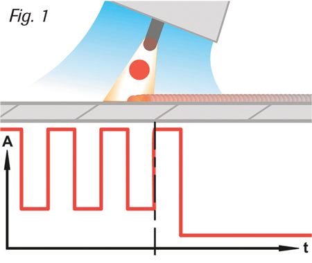
Modified pulsed-spray transfer starts with a conventional pulsed waveform and then combines it with a second waveform—or even another process —to achieve specific goals. Possible combinations include:
1) Pulse/short arc (Fig. 1), which provides maximum control over heat input for welding sections as thin as 0.24 in.*, as well as for root-pass welding.
*Minimum and maximum thickness possibilities depend on wire diameter and type.
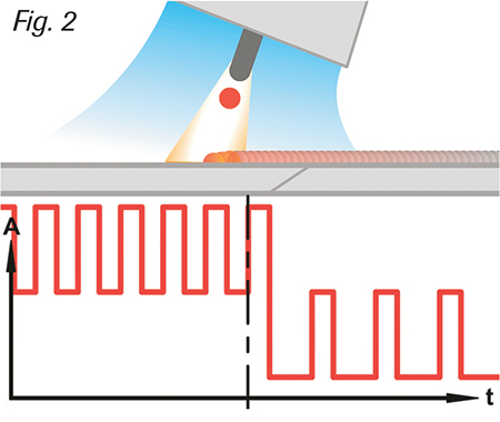
2) Pulse/pulse (Fig. 2), for welding material 1⁄16 in. and thicker* with great control over heat input, bead profile, bead appearance and travel speed.
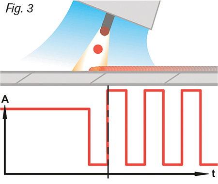
3) Spray arc/pulse (Fig. 3), for higher productivity on thicker sections while still preserving the ability to weld vertical-up without any weaving motion, which reduces operator fatigue.
As with spray-arc GMAW of aluminum, operators learned that they could improve pulsed-GMAW bead aesthetics by whipping the gun to create a GTAW-like bead. Unfortunately, whipping creates potential quality concerns, as operators quickly can go from good to poor fusion. Whipping also increases the possibility for stress risers—locations that concentrate weld fatigue and where cracks potentially start.
Conversely, the modified pulsed-spray transfer process inherently creates the desired stacked-dime bead appearance, as weldmetal deposition rates consistently vary when the system switches between transfer modes. The process eliminates the variables associated with gun manipulation, promoting uniform penetration throughout the length of the weld and minimizing issues related to stress risers. Further, the process enables fabricators to obtain premium bead appearance with fixed and flexible automation systems—particularly handy for circumferential welds on pontoons or for long seam welds on trailers.
Operator- and Supervisor-Friendly
Welding power supplies with complicated controls can alienate, intimidate and frustrate welders, supervisors and training managers, sometimes to the point where a company fails to take advantage of the technology it has purchased. Early generations of pulsed-GMAW machines often fell into this category. Outside of a few canned programs for the most common filler metals, users were required to combine programming and welding expertise to fine-tune waveform variables to a specific application.
The newest generation of pulsed-GMAW machines provides much more user-friendly controls, as well as a greater breadth of factory-set pulsing programs, commonly referred to as “synergic lines.” For pulsed GMAW, a machine might have synergic lines for the following grades of aluminum filler wire: 5356, 5183, 5556, 5554, 4043, 4047 and 1100. The human-machine interface prompts users to select and enter process variables such as shielding gas and wire type and diameter, and then select the desired welding process. Once entered, the welding machine (power supply and wire feeder) automatically determines process variables and delivers optimized arc performance with no advanced-process knowledge required.
Fig. 4—When using synergic control, the voltage-control knob provides what is commonly called trim control to fine-tune the arc cone emanating from the wire tip. Decreasing trim (shown here) moves the start of the cone closer to the weld to create a narrower bead.
To increase or decrease travel speed, operators simply adjust wire-feed speed accordingly. The power supply automatically adjusts all other process variables to maintain optimum arc conditions. This type of control, called “synergic control,” finds use in many of today’s advanced power supplies.
When using synergic control, the voltage-control knob provides what is commonly called “trim” control. To understand how this works, imagine the arc as a cone emanating from the wire tip (Fig. 4). Increasing voltage/trim moves the starting point of the cone closer to the contact tip so that the cone covers a wider area. Adding trim creates a wider, hotter weld puddle with better flow into the toes of the weld. Decreasing trim moves the start of the cone closer to the weld to create a narrower bead. Note that when making trim adjustments, the welder must consider the amount of filler metal required for adequate bead width and throat depth.
Synergic lines and synergic control can meet the needs of most aluminum fabricators. For special applications, such as fine-tuning heat input and custom-tailoring weld-bead size and the distance between pulse ripples, users can select different transfer methods and adjust the duration of each method. They also can transfer the program to other machines in the shop via flash drive. As an added benefit, some machines display actual parameters for both waveforms, which helps when establishing and documenting weld-procedure specifications.
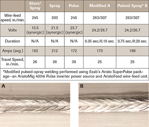
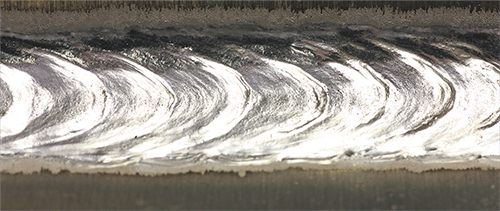
These images show the weld beads associated with the parameters for the modified pulsed-spray processes (A-B) in the table. They demonstrate that fabricators can reduce filler-metal costs by using a larger-diameter weld wire on thinner materials.
Lowering Filler-Wire Costs
As with any capital expense, acquiring a pulsed-GMAW power supply requires examining it in the broader context of each company’s operation. Companies typically purchase pulsed-GMAW setups to accomplish one or more of the following objectives:
• Increase competitiveness due to consistent weld quality and appearance;
• Address workforce issues;
• Improve productivity (faster welding speeds, better first-pass yield, less scrap);
• Automate their processes; and
• Reduce operating costs (lower utility bills, receive utility rebates, reduce filler-metal costs).
|
From Shavings to Savings Just as there’s a performance difference between conventional, pulsed and modified pulsed-spray welding, there’s a performance difference between standard and premium filler metals. In the case of aluminum wire, conventional 5xxx-series wires have a well-deserved reputation for generating aluminum wire shavings that build up in the wire-feeder drive rolls, liner and contact tip. As the shavings build up, they hinder feeding performance, create excessive consumable wear, cause more frequent burnbacks and increase the need for routine maintenance. Even worse, the problem creates a vicious circle: As aluminum particles flake off and embed in the gun liner, they score the wire and create additional shavings. Over-tensioning the drive rolls generates shavings, as does wire-to-wire scuffing, but the problem used to be inherent in the product. To address this issue, a new weld-wire manufacturing process (from AlcoTec) eliminates the microfines and surface abrasion generated during wire drawing. This minimizes or eliminates the shaving problem, greatly improving wire feedability and arc stability. These improvements result in less wear and tear on contact tips and less frequent replacement of liners. |
While some of these objectives are less tangible than others, the ability to reduce filler-metal costs is relatively easy to calculate. Because of the ability to control heat input with the pulsed and modified pulsed-spray transfer processes, fabricators can typically use a larger-diameter weld wire. Because larger-diameter wires cost less per lb., fabricators can save somewhere between 2 to 25 percent, depending upon alloy and packaging.
In addition, a larger-diameter wire can weld a broader range of material thicknesses. For example, an 0.047-in.-dia. type 5356 filler wire can weld materials 0.040 to 3⁄8 in. thick, while an 0.062-in.-dia. type 5356 filler wire can weld materials 0.125 to 5⁄8 in. thick.
To the Test
To demonstrate the flexibility of the modified pulsed-spray welding process, tests were conducted using 0.062-in.-dia. type 5356 filler wire. Welders deposited fillet welds using test coupons of 1⁄8-in.-thick type 6061 aluminum.
The results for the short arc/spray process (second column) can be discounted, as the process lacks sufficient energy for welding with 0.062-in. wire. The welds looked cold and lumpy.
To obtain a conventional spray-arc transfer, the wire-feed speed was increased to 300 in./min. However, obtaining a weld size similar to the pulse-mode sample—and to not melt through the workpiece material—required a travel speed of approximately 72 in./min., nearly impossible for a welder in a production environment. If the welder were to slow down to a manageable travel speed of 36 in./min., the risk of burnthrough becomes high, plus the workpiece material becomes overheated, the weld becomes hard to control and bead appearance is poor.
Conversely, the pulsed- and modified pulsed-spray transfer processes have no problem. Travel speeds remain manageable and heat input is controlled to prevent burnthrough.
For fabricators who want to reduce filler-wire inventory, and wire-changeover time and standardize on a single, larger-diameter wire, pulsed and modified spray-arc transfer can provide significant savings. MFView Glossary of Metalforming Terms
See also: Alcotec Wire Co.
Technologies: Materials, Welding and Joining