Automated Calibration Optimizes Multi-Laser System Performance
October 15, 2019Comments
Manufacturers often experience an inverse relationship between speed and quality, but when making parts for aerospace, medical devices and other complex applications, quality is fundamental. Any gains in output that compromise the safety or utility of the part aren’t gains at all.
 In the interest of faster production, additive manufacturing (AM)-equipment makers have been moving toward two-, and sometimes even four-laser setups. However, adding lasers can introduce complications quantitatively and qualitatively distinct from those of printing with a single laser.
Laser Alignment
 The addition of a second (or more) laser to an AM setup can raise concerns with scan-field alignment, particularly with aerospace components and other large parts. While one laser can individually print many types of smaller medical parts, such as orthopedic replacements, printing larger parts that take up most of the build plate often requires multiple lasers to work in concert. Any slight laser misalignment can have big consequences. In engineering terms, that means that each scanning system must accurately align to the other within less than 50 microns difference throughout the build plate.
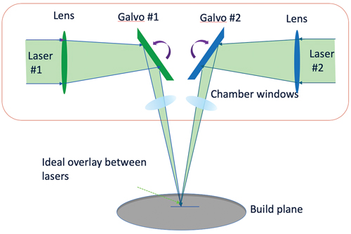
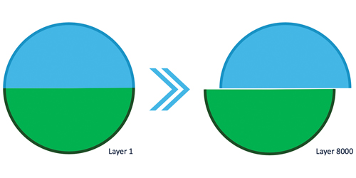
 In most systems, precisely aligning two laser spots (Fig. 1) requires external hardware. The alignment procedure often consists of burning marks on a substrate and measuring the outcome, a tedious process. In addition, AM shops must perform the calibration at the build plane, since any change in the distance between the scan head and the measurement plane will cause a corresponding alignment shift.
The System’s Thermal State
…represents another important variable when printing with multiple lasers. For example, consider a build chamber made from stainless steel, with the scan heads located 500 mm from the build plane. During a build, the chamber heats up; even a 15-deg. change in chamber temperature can cause the distance from the scan head to the build plane to change by more than 100 microns. Depending on the angle of incidence in the laser-overlap region, this temperature change alone can invalidate the calibration.
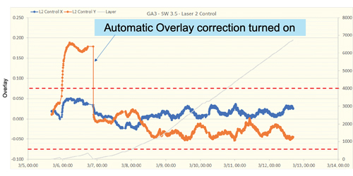
 As an engineered solution to these challenges, consider systems with in-situ laser calibration. By frequently comparing the optics of the two lasers, autonomous calibration ensures that they remain in agreement on where each other is pointing. On a typical job, this type of AM system will automatically check its laser alignment every few layers, which undoes any drift before it becomes a problem. We can test the effectiveness of this system in numerous ways.
 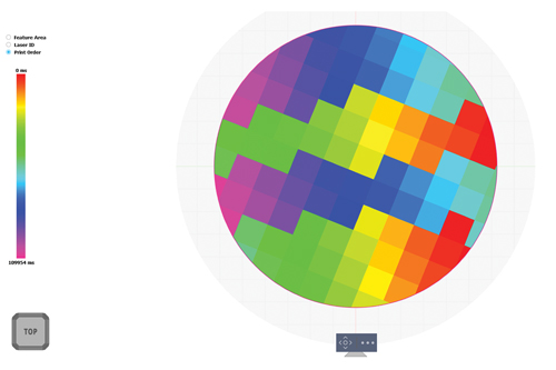 The increased production rate realized from multi-laser systems can be mitigated if one laser sees 100-percent utilization and the other sees less, say 50 percent. Shops must therefore pay close attention to laser scheduling—this means knowing the path of the lasers. In addition, engineers must examine how laser soot affects the scheduling, and how well the lasers coordinate their efforts when printing the contour and core of larger parts.
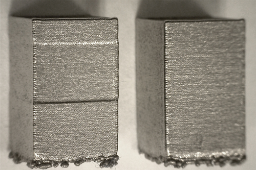
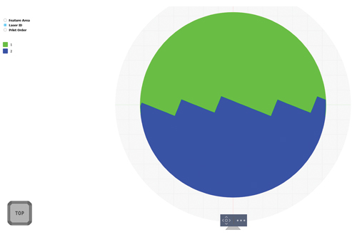 A crucial engineering question (with more than one answer) is how to subdivide the work between the lasers when each is building a portion of a solid part. Consider, for example, printing a cylinder, where one laser prints the entire contour while multiple lasers work on the core. Parts printed in this way will look good on the surface due to the seamless outer layer, however this approach can cause sub-contour porosity, with any structural issues hidden by the clean outer surface.