A New/Improved Press
Describing the operation of the retrofitted press, Hathaway notes that during a compression cycle, the bottom cylinder extends and stops with the bottom form just touching the part. Then, the top cylinder comes down to just above the part, and the part is then heated to allow forming. After heating, the top cylinder moves down so that the top form contacts the workpiece to begin compression. The motion controller precisely controls the velocity of both cylinders, while monitoring the force being applied during compression to ensure that it does not exceed a specific limit. As the top cylinder extends and compression begins, the motion controller causes the bottom cylinder to give way and retract at a controlled rate, ensuring a precision forming process.
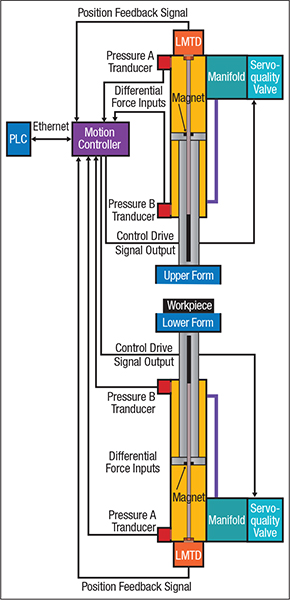
Block diagram of the hydraulic press with opposing cylinders.
The accompanying figure shows the block diagram of the upgraded control system. Cylinder-position information relays to the motion controller via a linear magnetostrictive displacement transducer (LMDT) with a synchronous serial interface (SSI) mounted in each cylinder. This transducer gives fast updates, approximately every 100 microseconds. For force feedback, the setup features two pressure transducers mounted in each cylinder, one on each side of the piston. The difference in pressure readings indicates the force applied by the cylinder.
“Prior to the system upgrade, the old valves responded with a significant amount of hysteresis and lacked linear control at low flow settings, making repeatable control practically impossible,” says Hathaway. “After upgrading the hydraulics, high-quality proportional servo valves were installed, enabling precise hydraulic flow control.”
Recipes Held in a Supervisory PLC
At the start of a compression cycle, the motion sequence downloads over Ethernet from a supervisory PLC, which holds the recipes for several different parts. The motion sequence parameters can easily be adjusted for production changeovers using the press’ new HMI.
Programming the new controller, developers relied on the RMCTools package from Delta Computer Systems, which features graphical tools for programming and tuning. Rather than using low-level machine code, users of RMCTools can set up motion by filling out forms and selecting intuitive options from pull-down menus.
With the motion steps programmed, next came tuning the system for optimal operation. Here, the RMCTools package provides software for analyzing the motion and adjusting control loop gains. A Plot Manager function displays motion parameters versus time, and a Tuning Wizard simplifies the tuning process.
“The manufacturer is very happy with the performance of the press upgrade,” adds Hathaway. “As a result of the closed-loop controller upgrade, the quality of the press’ output now is consistently high and the productivity of the press has improved by about 30 percent.” MF
Article contributed by Brad Smith, Delta Computer Systems Inc., Battle Ground, WA; www.deltamotion.com.
View Glossary of Metalforming Terms
See also: Delta Motion
Technologies: Pressroom Automation, Sensing/Electronics/IOT, Stamping Presses

 Podcast