Best Practices: In-Die Sensing
October 1, 2014Comments
Learn from this case study how one metalformer follows industry best practices when outfitting more than 500 dies with a variety of sensors, to ensure that the sensors live long, healthy and productive lives.
The highest levels of error-proof manufacturing are being achieved at Eagle Bend Mfg., Eagle Bend, TN. As part of Magna’s Cosma International Division, Eagle Bend has a varied portfolio of internal production processes including hot stamping, rollforming, transfer presses/automated tandem-press lines, laser trimming and welding. These activities are thoroughly supported with engineering software and technology including Catia V5, SDRC, Inventor and white-light scanning capabilities. The firm’s client base includes Ford, GM, BMW, Nissan, Honda, Toyota and Chrysler. With a plant size of 550,000 sq. ft. and more than 700 employees, the plant processes some 104,000 tons of steel per year and boasts annual sales exceeding $250 million.
Sensor Program a Serious Undertaking
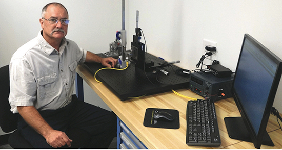 |
| Eagle Bend Mfg. sensor applications specialist Mike Williams shows off his fully equipped sensor-testing laboratory, which includes precision positioning equipment to help him determine the exact location where a given sensor must be mounted within a die in order for it to properly and repeatedly detect its target. |
Eagle Bend Mfg.’s implementation of a professional sensor program for error proofing required a capable and dedicated leader—meet Mike Williams, a toolmaker by trade, who became its sensor applications specialist. Williams began his career at Eagle Bend Mfg. in 1988 and was selected to attend the Magna Technical Training Centre in Toronto, Canada as a tool and die apprentice. After completing the 1-yr. training program, Williams returned to Eagle Bend to complete his apprenticeship.
As a newly minted toolmaker, Williams was assigned to the tasks of repair and maintenance of tooling, with some tool building as well. In addition to his exposure to the stamping side of the plant, he garnered experience in the assembly areas of the company, building and maintaining various pieces of assembly equipment.
In the summer of 2010 Williams went to work for a local tool and die shop where he built a variety of tooling, fixtures and gages. When he returned to Eagle Bend Mfg. in the spring of 2013 as a die-assembly toolmaker, in short time management selected him to become sensor applications specialist. Since that time, Williams and his company’s error-proofing technology committee have embarked on a major initiative to outfit more than 500 existing and new tools with a variety of sensors for die protection, including part ejection, short feed and part-quality detection. As of this writing, the job is about 25 percent complete.
Test Bench Extraordinaire
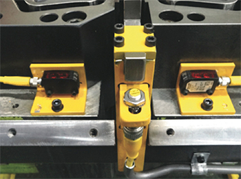 |
| Williams prefers to use reflective photoelectric sensors (two shown, flanking a short-feed sensor in the middle) for detecting part ejection. His choice of bright yellow mounts and cabling is meant to alert others in the plant that the area has sensors within it and to exercise caution when working nearby. |
With the full and uncompromising support of Eagle Bend Mfg. general manager, Ed Steinebach, the firm designed and constructed a state-of-the-art sensor-testing laboratory for Williams. The lab allows him to perform a variety of application tests required to ensure the proper implementation of sensors within tooling and assembly processes. Williams has all of the necessary equipment needed to filter through the various sensor options on his test bench. Precision positioning equipment helps determine the exact location where a given sensor must be mounted within a die in order for it to properly and repeatedly detect its target. That target can be a part or a tooling component.
Williams also uses the test bench to verify that the sensors will actually function within the die without having to mount them first in the tooling, and then experiment out on the production floor. This sensing-simulation process provides a way to investigate and innovate away from the actual tooling. Thus, when Williams is ready to actually mount the sensors in the dies he already has a very good level of confidence that the sensors will work in the pressroom, avoiding nuisance stops due to improper sensor selection and testing.
The First Priority of Any Good Sensor Program
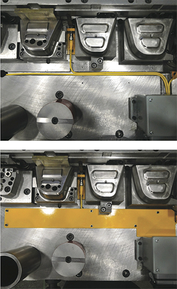 |
| Williams uses channeling and cover plates to protect sensor cables. |
… is to, as quickly as possible, implement sensors to monitor strip feeding and part ejection. Here, Williams has developed a uniform approach to feed monitoring by incorporating an inductive proximity sensor to detect the position of a spring-loaded block that is pushed into its final, fully fed position by the strip at the end of the feed cycle. He prefers to use reflective photoelectric sensors for detecting part ejection. Note in the accompanying photos the bright yellow color, used to alert everyone in the plant that the area has sensors within it and to exercise caution working near it.
It also is the duty of the sensor applications specialist to fully test photoelectric sensors for their ability to function within an oily environment in the die. This easily can be done by spraying the photoelectric detecting beam(s) using a hand-held sprayer to ensure that the oil will not fool the sensors into giving a false output. The one catastrophic mess to avoid is to have the part not be properly ejected from the die, and the photoelectric sensors fooled into sending a false ejection signal caused by the oil droplets.
Sensor Protection
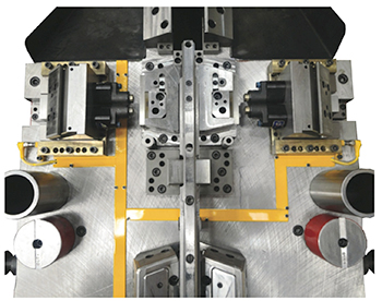 |
| The implementation of sensors to monitor cam position has become a routine application in many shops. Shown are two separate cams monitored for their respective returns with one inductive proximity sensor per cam. |
Throughout my 30 years of writing columns and articles for MetalForming on sensors, and consultations with metalforming companies of all sizes, I remain astounded as to the amount of sensor destruction that takes place in many stamping companies, whether from human error or outright negligence. Therefore, it is paramount that all sensor cabling be protected from being crushed, nicked or cut.
This can be done in one of two ways: machining channels for the routing of the sensor cables (when possible), or by using tubing to protect the feed sensor cable. When burying cables in machined channels, be sure to cover the channels with protective plates. Note how, once again, Williams uses yellow paint on the plates to warn everyone who will be working with the die that the area houses sensor technology.
In addition to using sensors to monitor strip feed and part ejection, many value-added-minded metalforming companies using cam motion within the die employ sensors to monitor cam position. Cams, used for forming, piercing, trimming, stud insertion and other operations, can tend to stick and not return to their neutral position when the die opens. Or, in some cases the cam may not arrive into its fully extended position. In either case, the implementation of sensors to monitor cam position has become a routine application in many shops. The photo (pg. 78) shows two separate cams monitored for their respective returns with one inductive proximity sensor per cam. Note how the sensor cables are immediately routed into channels.
Centralizing Cables is Non-Negotiable
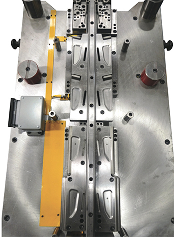 |
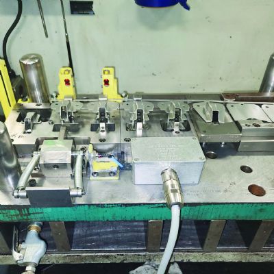
| Best practices requires stampers to centralize sensor cables into one connector. Note here how Williams routes sensor-cable channels underneath the sensor connector box. The cables then enter the box and the individual sensor wires connect to their appropriate pins on the connector. |
The centralization of all sensor cables into one connector is a non-negotiable must in metalforming shops following best practices, and Eagle Bend Mfg. is no exception. Note in photo 6 how Williams routes sensor-cable channels underneath the sensor connector box. The cables then enter the box and the individual sensor wires connect to their appropriate pins on the connector.
Stampers select from two popular styles of connectors: a military-style round connector and a rectangular connector. Either way, the connector chosen must be robust and able to withstand the shocks and vibrations of the stamping environment.
To borrow a well-known phrase from the NASA Apollo Moon Missions, “failure is not an option,” and to use it to describe the attitude within Eagle Bend Mfg.’s sensor program would be an understatement. MF
Note: Mike Williams and Ed Steinebach will describe their sensor program in more detail at a conference presentation at FABTECH 2014 in Atlanta, on Wednesday, November 12. Learn more and register to attend by visiting www.fabtechexpo.com.View Glossary of Metalforming Terms
See also: Tecknow Education Services, Inc.
Technologies: Sensing/Electronics/IOT, Tooling
Comments
Must be logged in to post a comment. Sign in or Create an Account
There are no comments posted. Sensing/Electronics/IOT
Work-Instruction Software Enables Workers to Activate, Monit...
August 5, 2024
Press Controls and Sensors Series Part 4: Die-Protection Tro...
Jim Finnerty February 9, 2025