


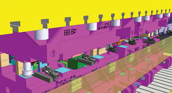
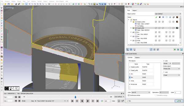
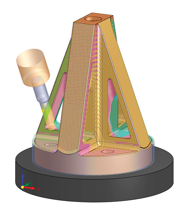
Long employed for cold forming and hot forging simulation, Deform is ideal for sheet metal applications including deep drawing, stamping, coining, blanking, ironing, bending and joining. Manufacturers regularly use the software to predict deformed shape, work hardening, springback and the risk of cracking across progressions. Deform also proves popular, say company officials, for modeling of blanking operations, where users optimize shearing behavior while minimizing burrs and other undesirable features. Advanced solid meshing tools allow coined geometries to be resolved with fine feature detail.
The Deform interface is tailored for designers and engineers, even those with no finite-element analysis (FEA) experience. A guided workflow simplifies the setup of multiple-operation process chains. Users may incorporate heating, forming, joining, testing and/or die-stress analysis into a single simulation. Projects reportedly can be reused and modified with ease, enabling quick evaluation of many design iterations.
The projects also serve as the foundation for design of experiments and optimization studies. These studies enable users to troubleshoot problems, optimize designs and test process robustness.
The software’s FEA technology provides valuable information about process output early enough in the development cycle to ease any changes that must be made, according to company officials. This is accomplished without the need for making tools, consuming machine time, scheduling manpower and buying raw material for shopfloor trials.
User-Requested Enhancements Added, Plus New Costing Functionality
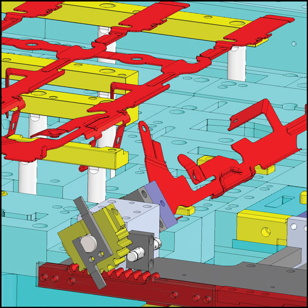 |
| Along with the other motion types included in Logopress3 Die Debugger, a new traction type has been added, easing motion simulation of gears, rollers, and rack and pinions. |
Logopress3
Version 2019 SP0.5 of Logopress3 die design software, from AutoForm Group and distributed in North America by Accurate Die Design Software, Inc., now includes a costing module that helps determine the cost of the tool based on material cost. This new costing functionality is available to users while in the strip layout or tool assembly areas of the software.
A strip assembly easily and quickly can be inserted into a tool template that already contains plates with predefined material types and sizes. These plates, along with the die set, then can be easily modified to whatever size the user wishes by simply double-clicking anywhere on a plate and adjusting the dimensions of that plate. Depending on the design intent of the user, this change then updates either that plate and related plates, or it updates the entire assembly of plates, according to company officials.
At the request of users, the Round Draw module in Logopress3 now can run with nonflanged cylindrical parts, such as parts to be created in a transfer press or those whose stretch web would be pulled into the draw cavity. Additional inputs have been added to this module, such as the option to enter a friction coefficient and another to enter a user-defined stripper force. Another new option allows the display of the maximum critical load at each draw station in the strip assembly, beyond which carries the risk of rupture.
To keep the software’s Die Debugger portion simple and rapid to set up, Logopress3 added tools to provide two new motions, say company officials. The first new motion allows the motion simulation of a component via traction or friction. Component applications include gear mechanisms, rack-and-pinion assemblies, and rollers. Also added are tools for the rapid setup of a connecting rod and crank motion, enabling Die Debugger’s movement of a slide or other piston-type mechanism.
Logopress3’s nesting software has been improved to support multiple sheets of material. This new multi-sheet mode automatically uses as many sheets as needed to place all the parts selected by the user for nesting. This update has been rolled out to users of the nesting software as well as those who have the die design software.
New GUI with Unified Pre-, Post-Processing Capabilities
Dynaform Version 6.0
ETA, Inc. (Engineering Technology Associates, Inc.), announced the latest release of its Ansys LS-Dyna-based Dynaform Version 6.0 die-system-simulation software. Dynaform 6.0 offers an all-new graphic user interface (GUI) with unified pre- and post-processing capabilities. Users quickly can conduct sheet metal stamping simulations to estimate the blank cost and formability of stamping parts using guided process wizards.
New features offered inside of Dynaform 6.0 include a simulation data manager; multiple windows for multi-stage simulation; large stamping simulation model with as many as 10 million elements; and a geometry manager.
Also new: instant and dynamic section cuts; Tata Steel forming limit diagram; Microsoft PowerPoint and Excel-based automatic report generation; automatic mesh generation from surface data; and a process wizard for blank-size engineering.
The software also now provides a tree structure for blank-size engineering, formability simulation and part on/off in the display area.“The new, simplified GUI features and process in Dynaform 6.0 will improve the efficiency and productivity of stamping engineers with no prior experience in stamping simulation,” says Dr. Akbar Farahani, CEO of ETA, commenting on the software’s ease of use.
Part-Unfolding Upgrades, Reverse-Engineering Enhancements and More
VISI 2020.1
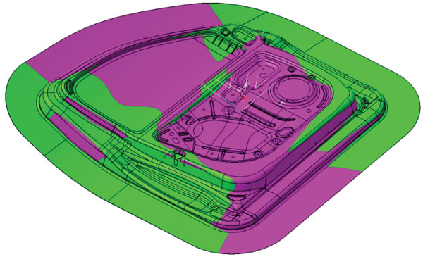
The Undercut option in VISI 2020.1 displays a part in three colors, representing the top, bottom and vertical faces. Users can define an angle up to which the faces are considered to be vertical. This graphical representation also can be activated during modeling operations.
TST Tooling Software has just released VISI 2020.1, offering several new and enhanced features that continue a dedication to specific CAD/CAM features for the made-to-order tooling industry. Included is a new graphical representation to support designers when validating models for manufacturing. For example, Undercut\Accessibility shading offers the ability to define the default display of parts using three colors to represent the top, bottom and vertical faces. Users can define an angle up to which the faces are considered to be vertical. This useful graphical representation also can be activated during modeling operations. Also, users can now set transparency for one or more faces of a solid or sheet in the Faces Attributes manager, which provides an enhanced graphical representation on solid bodies.
To save time, the Picking on Edges feature has been enhanced by providing new options in the contextual menu, speeding the picking of edges in a loop on solid bodies. A new option enables automatic selection of all edges starting from the selected face. This is useful, for example, when adding radii on corner edges of a pocket or on edges of a punch. This VISI version also features an improved dynamic section command to create sections around an axis or along a curve.
The software’s Analyze Profile function allows users to analyze profiles to find gaps, small elements and cusps; find eventual inconsistencies such as overlapping sections; and obtain information about the profile (number of elements, length, etc.). And, users now have a major advantage when saving plot-view pages with the ability to include associated solids data.
VISI also provides enhancements for reverse-engineering needs, including more options for loading point-cloud data, and working around point-data noise. An Adapt Mesh to Element feature allows users to edit and automatically adapt the selected mesh to a defined entity, useful because a detected area can be defined as a correct geometry (slot for instance), or users can adjust and adapt the border of a specific scanned area by using a segment or curve. Other features also support reverse engineering by enabling creations of plane and radii surfaces from mesh.
New part-unfolding features include blanking and management of parts with non-linear bends, enabling a user to modify the original part and rebuild the other unfolded parts in subsequent stations in one click. The goal: a robust and simple solution for studying and modifying a part by preserving the linking between the different unfolding steps. According to company officials, this capability is extremely useful as it updates all studied parts in a single click, offering time savings during die design and modification.
New Capabilities in Tool Design and NC Programming
Cimatron 15
The automated five-axis roughing capability in Cimatron 15 facilitates maximum material removal in the shortest amount of time, say company officials, thus helping to accelerate production.
Cimatron 15, from 3D Systems, is the latest version of this CAD/CAM software that addresses the tool-making process from quoting to design, including application of engineering changes and NC programming.
Cimatron 15 introduces hundreds of new and enhanced capabilities for both tool design and NC programming, according to company officials, plus new mill/turn and conformal cooling applications and analysis tools. New, enhanced and automated NC programming capabilities reportedly enable manufacturers to shorten programming and machining time. A new Mill/Turn application in the Cimatron NC environment enables users to program mill/turn and turning machines within the same familiar environment. And, new and enhanced tool-design capabilities enable more rapid design and improved manufacturing quality, say company officials.
The software provides an improved cooling application, say company officials, while the software continues to support hybrid manufacturing environments with subtractive and additive features.
Catia-Embedded Tools for Build of Draw and Form Developments
AutoForm-ProcessDesignerforCatia
AutoForm has introduced AutoForm-ProcessDesignerforCatia, a Catia workbench of tools for efficient building of high-quality draw and form developments, according to AutoForm officials. It features streamlined and wizard-guided workflow, as well as surfacing tools specifically tailored to the stamping-die process design. With integrated quality checks and analysis tools, users can ensure the quality of developed surfaces.
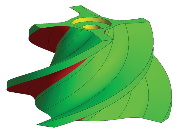
 |
| The vector field generated by AutoForm-Compensator is applied in AutoForm-ProcessDesignerforCatia to produce a proportional and smooth compensation. |
The software reportedly has been benchmarked for complex developments as taking one-fifth of the time needed to accomplish the same designs using native Catia functions. While results vary, such success can be achieved by any level of native Catia user, as few native features are needed, according to AutoForm officials.
AutoForm-QuickLink provides the two-way pipe between CAD and simulation, facilitating accurate validation of developed process and tooling surfaces, as well as providing guidance for modification of tooling surfaces for acceptable panel outcomes.
AutoForm-ProcessDesignerforCatia reportedly excels in high-quality compensation based on accurate predictions, with all the necessary functionality needed to compensate dies for Class A as well as inner or reinforcement panels. Compensation can be carried out based directly on compensation loops from the AutoForm-Compensator, the users’ experience or even a scanned part. Compensation capabilities include direct and proportional compensation; smoothing of the compensation vector field; reference to target compensation for Class A panels; advanced preparation for milling release; and integrated quality analysis.
In addition, the software’s functionality in providing for draw and form tool surfacing from the ground up reportedly enables simple and rapid updating for complex developments triggered by product changes. MF
View Glossary of Metalforming Terms
See also: ETA (Engineering Technology Associates, Inc.), Autoform Engineering USA, Scientific Forming Technologies Corp., Accurate Die Design Software, Inc., LOGOPRESS
Comments
Must be logged in to post a comment. Sign in or Create an Account
There are no comments posted.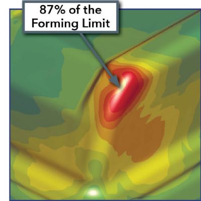 Software
Simulation Software Elevates Die-Development Efficiency
Brad Kuvin Tuesday, June 10, 2025
 Materials
Tooling Up for AHSS: Know the Material, Mind the Simulation
Lou Kren Tuesday, April 1, 2025
 Software
AI-Powered Automation Promises to Slash Machine-Tool Program...
Wednesday, March 5, 2025