Temperature Effects During Cold Forming
February 12, 2021Comments
In our previous Cutting Edge column, we discussed how forming and cutting operations generate heat in sheet metal. In large-panel stamping operations, a typical tandem transfer-press line may operate between 8 and 25 strokes/min., so it only takes 4 hr. to stamp some 2000 parts. Considering that every part generates a significant amount of heat, and some of that heat becomes trapped in the die, die temperature quickly can increase.
Why is This a Problem?
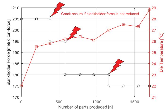 A study conducted at a European automotive OEM shows that a door inner stamped at 8 strokes/min. causes tool temperature to increase by 6 C after 1700 strokes, over about 3.5 hr. To stamp parts without failure, blankholder force had to be reduced after several hundred strokes (Fig. 1).
In a typical die buyoff, most companies will not stamp this many parts. After the stamper accepts the die, cracks may still appear during the ramp-up tests (also called stress tests), after a few thousand strokes. These cracks typically could be avoided by applying more lubricant―if the stamper does not have a dry press shop―or by reducing the blankholder force. While both solutions may cure the cracking problem, wrinkling might result.
Most die designers use finite-element (FE) simulations to check the feasibility and robustness of a designed process. They typically base design decisions on forming-limit diagrams (see the Cutting Edge column in the February 2020 issue of MetalForming).
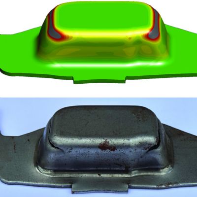
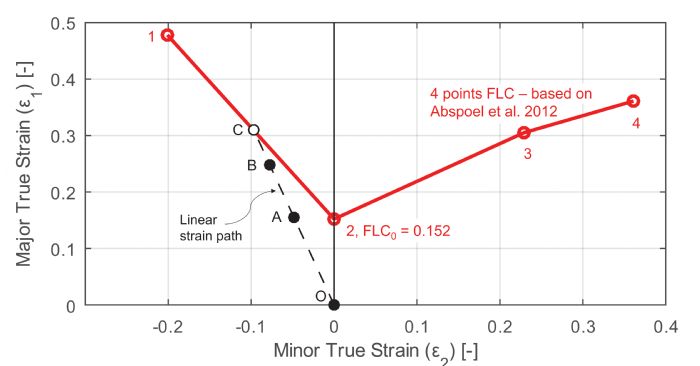 Fig. 2 shows the forming-limit curve (FLC) for 1.6-mm-thick DP800 steel. Points A to C represent the strain distribution of some random elements in the process. The failure criterion of point A is 50 percent, as the point is halfway from origin to the FLC (point C). The failure criterion of point C is exactly 100 percent, meaning that the part cracks at point C. If a process has a maximum failure criterion of 0.7 to 0.8 (70 to 80 percent of the FLC), it generally is assumed to be production-ready. Point B shows a 0.8 (80-percent) failure criterion.
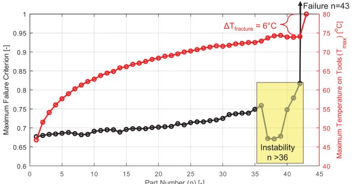 Fig. 3 shows the maximum temperature of the punch radius (the hottest part of the die) and the maximum failure criterion for 43 consecutive strokes. The conditions were simulated for a mechanical press with a 916-mm stroke running at 8 strokes/min. As seen, the first stroke resulted in a failure criterion of 0.68, considered “safe” by most die designers. This value increases to about 0.75 in 35 strokes—still safe. Then a brief period of instability is observed where the failure criterion reduces for a while. This instability also is observed in other simulation models with higher stroke rates and using link-motion presses. After the instability, the failure criterion surpasses 1—the part has failed. Here, the 43rd part exhibited splits. In most cases, when the part fails the simulation software calculates an increase in punch temperature (Tfracture in Fig. 3); this may not be observed in the press shop.
 The simulation model in Fig. 3 took about 7 hr. of CPU time and created a 14-GB results file, as opposed to about 5 min. for a single-stroke simulation and a 500-MB results file. The CPU time is directly proportional to the number of cycles simulated. As shown in Fig. 1 and verified through feedback from metal stampers, cracks due to die heating typically occur after a few hundred cycles. Two concerns: