Using Simulation Software
December 2, 2020Comments
...to navigate the perfect storm of die development: increased part complexity, stronger steels and compressed customer timelines.
Facing the “perfect storm” of die design and development—dramatic increases in stamped-part complexity along with compressed customer timelines—led the management team at 3-Dimensional Services Group, in 2015, to invest in new simulation software. The company now regularly calls on the software to help manage blank development, evaluate stamped-part and process feasibility, and generate and simulate alternative die-face designs.
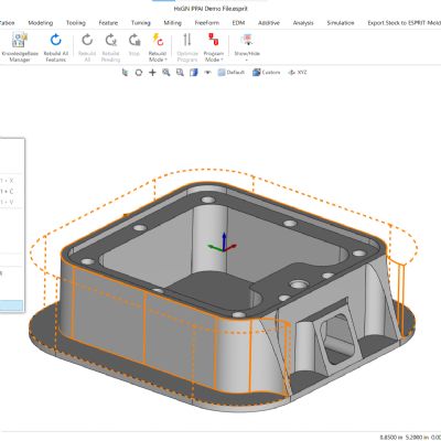
 “Simulations are critical now,” shares Daniel Smith, a salesman for 3-Dimensional Services Group, a diversified group of companies offering a multitude of capabilities including CNC machining, stamping, laser cutting and robotic welding, plastic injection molding, welding, waterjet cutting, hydroforming, and prototyping. “We use the software (a trio of modules from AutoForm) to efficiently validate tooling designs prior to putting die blocks into a CNC machine. The ability to validate our blank and die designs saves us countless hours of shop time, much of which would typically consume costly overtime hours, and cuts way down on material waste.”
Streamlining Tryout
3-Dimensional Services Group operates out of four facilities and a combined 350,000 sq. ft. of manufacturing space housing nearly 400 employees. Die development occurs at its headquarters facility in Rochester Hills, MI, and at its Urgent Design & Manufacturing facility in Lapeer, MI. While it serves a host of end-use industries including appliance, aerospace and defense, automotive is its largest market, keeping it busy developing components and assemblies for body-in-white structures, seating and chassis systems, and the like. The company operates some 160 presses, maxing out at 5000-ton capacity; it has 14 presses 1000 tons and up.
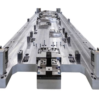
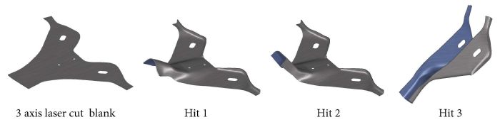
“We don’t develop or run any progressive dies here, it’s all hand-transfer work,” says Smith. “If a part requires four or five hits, that means designing and developing four or five separate dies. The more difficult the job—whether due to material type or part complexity—the more material, and time, we would waste in tryout.”
Eliminating that waste led the firm to purchase five seats of AutoForm. “I’m told we have more solvers than some of the OEMs,” Smith says. Its team of die designers use three AutoForm modules: StampingAdvisor, DieDesigner and Compensator.
“We use them constantly,” says Primo Tongko III, CAD room senior tool-design leader. “Before AutoForm, everything was done manually. Merely developing a blank could take weeks and consume a lot of material. Now, every part that comes in we run through AutoForm.”
Evaluating Part and Process Feasibility
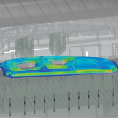
AutoForm-StampingAdvisor enables designers at 3-Dimensional Services Group to quickly evaluate part and process feasibility, and determine blank shape, material utilization and blank cost. It identifies any risk of excess thinning or splitting during stamping, and the potential for wrinkling.
“We use the software for early feasibility evaluations based on part geometry,” says Tongko. “I can modify the part design and within minutes the software automatically will generate the blankholder surface and addendum. It also will identify potential formability issues and create the optimum blank shape, while calculating material utilization and blank cost.