
The Power of Parametrics
SolidWorks-based Logopress3 3D design software is parametric software as opposed to direct modeling software, explains Ray Proeber, president of Accurate Die Design (www.accuratediedesign.com), New Berlin, WI, a Logopress3 reseller and user. 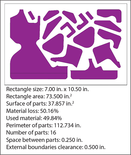
“Parametric software allows for a great deal of automation during die design, while direct-modeling software does not,” Proeber explains. “Because of this, Logopress3 automatically links certain things in the die to allow for simple updating or changing, including 2D drawings linking to the 3D model. Also, it allows for true animation of the die as if it were operating in the press, including dynamic interference detection while the die is operating.”
Practically all parts have one change or another made during or after the design process, such as an engineering change where features are added, or perhaps the parts may undergo development changes where the flat blank must be tweaked to bring a dimension closer to nominal.
“With the parametrics in SolidWorks and Logopress3, many changes can be made simply by opening the part model, making the change to the part and then telling the die to update by clicking the Update icon,” Proeber explains. “In seconds, the strip layout automatically updates along with 3D models of the punch, die block, stripper and backup plates, as well as the finished assembly and 2D drawings.”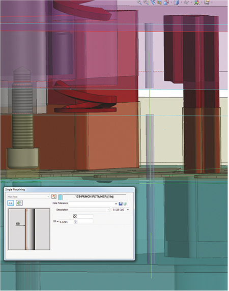
Logopress3 provides a preview of a stack of three wire-EDM start holes simultaneously being created in the die block, stripper and punch retainer.
Another example of automation in some parametric software, points out Proeber, is the ability to reuse a substantial amount of data when completing a new die design that has similarities to a previous design. Taking advantage of that capability, Logopress3 has a command, “Save as with new project name,” with the project name referring to the job number or tool number, or whatever method a company uses to differentiate between jobs.
“Due to the power of parametrics,” according to Proeber, “Logopress3 customers can complete new designs similar to old designs in a matter of hours using this tool.”
Logopress3 2015 offers many new features. For example, catalog components have been added to the library, including ball-lock punches, pilots and retainers.
“When a catalog component is added using Logopress3, it simultaneously cuts all holes through all plates in the die and also inserts and mates the component into the hole,” says Proeber. “The holes are all cut at the part level and not at the assembly level, so they appear on the 2D drawings.”
Logopress3 also recently added the ability to perform part nesting. While originally developed to nest wire-EDM punches on a common punch burn block, the feature can be used to nest shims or inserts, or even for production parts on waterjet and laser cutters.
Of course, to wire-EDM components, one needs to have wire-EDM start holes. Logopress3 provides flexibility in how the user wishes to create wire-EDM start holes, according to Proeber, by providing five methods to choose from: a 2D sketch, a planar surface, an extruded surface, an extruded body or a thin extrude. Wire-EDM start holes add to hole tables automatically.
“The start holes even can be added to a larger hole to be made to size via wire-EDM,” says Proeber. “For example, if a bushing in a die block will be fabricated to 0.500-in. dia. using wire-EDM, the hole table will call out the fact that there is a 0.125 dia. start hole in this hole and that this hole is to be wire-EDM fabricated to 0.500-in. dia. This way the cam operator knows that a start hole is to be drilled at this position and the wire-EDM operator knows the size of the hole to be made along with the size of the start hole and its position.
Hundreds of Enhancements in Design and Build Software
TST Tooling Software Technology offers VISI V21.1 from Vero Software for tool, die and mold design and build. Updated CAD features include Part Revision Management, where users can manage model changes after they have been released for manufacture.
TST Tooling Software Technology LLC (www.tst-software.com), Clarkston, MI, has announced the release of VISI V21.1, the latest version of software for tool, die and mold design and build. The software’s maker, Vero Software, reports more than 340 enhancements in this version. 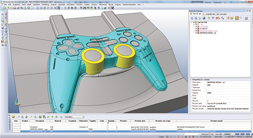
Updated CAD features include a new process for managing multiple instances of the same geometry within an assembly. For example, multi-insert dies and molds can be managed with a single ‘master’ part, which automatically will update all references of the same geometry should any part modification be required. Standard catalogue components will be managed by this multi-instance technology.
The release also includes motion-study simulation tools allowing the user to define timelines that control movement for various groups of components. With these tools, physical interaction of model geometry can be detected and the results of complex mechanisms simulated and investigated—ideal when validating tool design and checking for potential collisions with slides, cams and lifters.
Other CAD highlights include Part Revision Management, where users can manage model changes after they have been released for manufacture. A revision history automatically generates when a model has been released with the model geometry automatically locked. Any change to a released model will create a copy of the data and update the revision number, providing a history track and ensuring that part manufacture remains up-to-date. 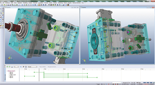
VISI V21.1 also includes motion-study simulation tools, allowing the user to define timelines that control movement for various groups of components. With these tools, physical interaction of model geometry can be detected and the results of complex mechanisms simulated and investigated.
The VISI 21.1 release also focuses on machining, including a new look for the CAM Navigator and command consolidation, and new dialogue-box consistency within all milling operations, all of which dramatically simplify toolpath generation, according to Vero Software officials. Feature-tree grouping, management of multiple setups/ features, and drag-and-drop capabilities within the tree ease navigation. All features within the tree can be moved, edited and mirrored. With a new dedicated Undo mechanism for CAM, user mistakes easily can be rectified.
Version 21.1 also introduces the next generation of CAM toolpaths for VISI machining. The 2D milling operations have been consolidated and include many new options. Remachining on a 2D toolpath is one highlight, where a simple milling operation now bases all remachining on the previous operation. This means that all the correct areas are machined, even on flat areas of the toolpath, according to Vero Software officials. Full collision checks on all lead-in and retract movements ensure that 2D toolpaths are efficient.
The Die Design and Simulation Software Experience Compare the latest developments in die-design, development and simulation software at The Die Design and Simulation Software Experience presented by MetalForming magazine, May 27-28, at the Somerset Inn in Troy, MI. You’ll be privy to case-study presentations describing successful software-implementation projects; keynote presentations on state-of-the-art die-design, development and simulation software innovations; and software demonstrations from leading suppliers. The event also offers the opportunity to network with software experts and meet engineers and die designers from other metalforming companies also interested in new developments in die-design software. For more information or to register, visit www.metalformingmagazine.com/diedesign. |
Wire-EDM developments in the new software include the introduction of smart operations that analyze feature geometry and determine the best method of cutting. Other enhancements include the addition of multiple-slug retention methods and ‘manual moves,’ which can be added into a work sequence for repositioning nozzles to avoid fixtures or to move from one cut to another.
Optimization, Automation Upgrades in New Design-Software Release
CimatronE 12 die-design software, just released by Cimatron Technologies Inc. (www.cimatrontech.com), Novi, MI, provides greater automation and streamlined workflow; safer, more confident and optimized results; improved process management; enhanced ease of use; and significant time savings, according to company officials.
As an example, a new fastening tool allows automatic creation of a wedge (custom-shaped or manually defined) on a selected face of an edge and its cutting object. And a simplified and quicker insert design enables users to efficiently create forming and bending punches. All standard aspects of the insert are automatically created, as are a new insert part file, cutting object and reliefs. All dimensions can be managed and the cutting object’s design verified.
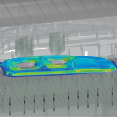
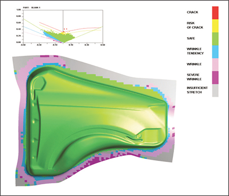
Advanced constraints in E 12’s Blank and Blank on Binder tools reportedly offer more accurate results with a new option that imitates the actual elements used in the shaping of the part, including pressure pad, draw bead, blankholder force and constrained face. And the software’s new ECO manager provides an accurate assessment and seamless incorporation of an unlimited number of engineering changes into an existing model. MFView Glossary of Metalforming Terms
See also: ETA (Engineering Technology Associates, Inc.), Accurate Die Design Software, Inc., CAMBRIO/Cimatron, LOGOPRESS, TST Tooling Software Technology, LLC
Technologies: Software
 Webinar