David Smith David Smith
President

Manual Bolting vs. Hydraulic Clamping—Press Uptime is the Key Measurable

June 1, 2013
0
Comments


Metalformers should understand that hydraulic clamps are not required for quick die change (QDC). They should, however, consider automatic clamps whenever die-change times exceed 20 min., or when manual bolting fails to achieve sufficient press uptime. Further, variations in manual bolting torque may not attain safe and consistent die-retention forces. Torque variation can cause process variability in some operations. Of course, when manual bolting cannot be accomplished safely and consistently, power clamping offers a good alternative.

Hydraulic clamping systems often employ air-over-oil intensifier pumps to provide hydraulic pressure. These simple systems prove dependable, provided the metalformer follows recommended maintenance procedures. Large systems, such as those on transfer presses with many clamps applied simultaneously, require large volumes of pressurized hydraulic fluid. Here, an electrical-motor-driven pump may be used to supply the required fluid volume. A hydraulic accumulator may be used to quicken clamping time.

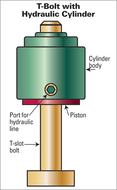
Fig. 1—A hollow-piston cylinder clamp essentially is a hydraulically powered nut. The hydraulic unit screws onto a standard T-slot bolt. The piston in the hydraulic unit applies downward pressure against the die-clamping surface (not shown) as does a conventional nut when tightened.
A low-pressure hydraulic switch is a normal safety feature of air-over-oil and motor-driven hydraulic-pressure sources. By monitoring for a loss of hydraulic pressure, a number of failure modes can be detected and the press stopped. Low-pressure safety switches vary in their setpoints—80 percent of the system’s operating pressure is typical.

General Safety Considerations

All automatic systems should be of failsafe design—that is, the die cannot become detached nor shift position on the ram or bolster during press operation. This could occur due to a failure of the clamping-power source or by command to release the clamps with the press in motion. To avoid this occurrence, good designs incorporate some or all of these safety features:

• Dual hydraulic power sources across diagonal corners of the machine, much like the dual-brake system on automobiles;

• Pressure switches to detect a loss of holding force;

• Automatic press shutdown in case of loss of pressure;

• Over-center toggle-locking clamps that will hold in case of a loss of pressure;

• Hydraulic clamps with built-in check valves to prevent fluid release in case of a pressure failure—these require a second hydraulic line to release the pilot-operated check valve;

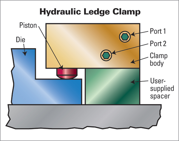
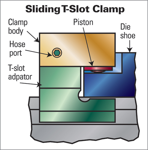
Fig. 2—Hydraulic ledge clamps feature a user-supplied spacer block, and fasten directly to the press ram or bolster by cap screws. Hydraulic fluid flows through internal drilled passages, minimizing the need for external hoses and piping, and eliminating potential sources of leaks.

• Employment of the wedge-and-ramp locking principle used to retain tapered-shank drills and reamers in standard holders—also requires the application of pressure to a second hydraulic line to unlock the wedges and release the clamp; and

• Limit switches to detect the proper clamp position, and proximity switches to monitor proper positioning of the die and press slide for clamping.

Safety is paramount in any die-clamping system. Should the die shift or fall from the press, severe die and/or press damage is likely to occur, not to mention the potential harm to operators. Over the years, many unexpected and needless pressroom accidents have occurred, some attributable to clamping-system failures that could have been prevented by proper system design and use.

Hollow-Piston Cylinder Clamp

This type of clamp (Fig. 1) essentially is a hydraulically powered nut. The hydraulic unit screws onto a standard T-slot bolt. The piston in the hydraulic unit applies downward pressure against the die-clamping surface (not shown) as does a conventional nut when tightened. The face of the piston features a captive, spherical, swiveling washer to compensate for irregular and tapered clamping surfaces; a hose attached to the cylinder port supplies hydraulic pressure.

A variation of this type of clamp uses a compact spring that contains a stack of dish-shaped Belleville spring washers to supply the required holding force. This clamp releases by the application of hydraulic pressure.

Hollow-piston cylinder clamps gain favor for QDC retrofit projects, since operators can adapt the clamps to a variation in clamping heights just as they would adjust a screw and nut. When adjusting the position of the hydraulic nut on the screw, the operator must be sure that sufficient piston travel exists. To avoid problems, shops should use a constant clamping height for all dies. The hydraulic nut may be pinned in place to avoid incorrect adjustment. Instruct all personnel responsible for safe press operation to ensure there is sufficient piston travel, including a safety factor.

Hydraulic Ledge Clamps

Fig. 3—Sliding clamps install easily in existing T-slots without bolster or ram modifications. Typically, 0.157-in. clearance is provided between the retracted pistons and the die-clamping surface. The hydraulic piston is a single-acting spring-return type; hydraulic pressure is applied through a standard port fitting.
…prove popular for new and retrofit applications. The clamp body (Fig. 2) and user-supplied spacer block fasten directly to the press ram or bolster by cap screws. As many as six (or more) individual spring-return pistons are available in this design. Hydraulic fluid flows through internal drilled passages, minimizing the need for external hoses and piping and eliminating potential sources of leaks.

For additional safety, ledge-clamp setups can be supplied as a split system supplied by two individual pressure sources. Some designs are supplied with hydraulically controlled check valves that require separate hydraulic pressure to release the clamp. The hydraulic ports are shown in the clamp body.

The clamping surface on the die shoe or subplate must be of a standard height to permit interchangeability with a variety of dies. The standard clamping height chosen determines the thickness of the user-supplied spacer block. Typically, 0.50-in. clearance is provided between the retracted pistons and the die-clamping surface. Each application requires individual evaluation. Ledge clamps that are bolted in place must provide ample piston-travel clearance in excess of the lifting stroke when using bolster roller lifters.

Sliding Clamps

Another common option for retrofitting existing presses with hydraulic clamping is use of sliding clamps (Fig. 3). Noteworthy features include:

• Easy installation in existing T-slots without bolster or ram modifications;

• Ability to clamp over a plate or ledge without the need for U-slots in the die shoe or subplate;

• The clamps are available from several sources; and

• They are well suited to most light-duty short-run jobs.

 The automatic traveling die clamp attached to the press slide of a large transfer press avoids the cost and weight of a sub plate mesuring the width of the press ram for each die.
The T-slot adapter is available for several standard types of T-slots. The standard clamping height chosen determines the finished height of the user-supplied spacer block. Typically, 0.157-in. clearance is provided between the retracted pistons and the die-clamping surface. The clamp body attaches to the T-slot adapter with screws. The hydraulic piston is a single-acting spring-return type; hydraulic pressure is applied through a standard port fitting.

An optional design employs a second port and a hydraulically controlled check valve to prevent the release of holding force in case of a line failure. The clamping surface on the die shoe or subplate must be of a standard height to permit interchangeability of dies.

Automatic Traveling Die Clamps

To enable automatic die change in transfer presses and tandem lines without the extra expense and weight of an adapter plate measuring the width of the press ram, stampers can opt for automatic traveling die clamps (Fig. 4). Shown is a complex automatic die-clamping system attached to a press slide. An electrical motor with a gear head drives the mechanism that positions the clamp. With the die in the press, and the press closed, the motor drives a flexible track with a clamp on the end into position to clamp the upper die in the press. While these systems can be expensive and somewhat complex when compared to a clamp that simply slides or swings into position, they prove very cost-effective in applications where operators struggle with hand-positioning clamps on large presses. Here, die-setter safety alone can justify the cost of the system.

It is essential to have a locating-pin system position the die clamping slots in alignment with the traveling clamps. Again, the purpose of the traveling clamp is to avoid the need for a subplate the width of the press ram for each die. The traveling clamp will engage and secure milled pockets in the upper die shoes.

The example shown (in Fig. 4) uses an electric motor and a gear-reduction drive with a sprocket system driving a rigid chain to move the clamp. Other positioning systems may use leadscrews or belt-drive methods. Designs use hydraulic or electric clamping. The power source to move the clamp into place may be an electrical motor, air motor, hydraulic cylinder or air cylinder.

Engineering Retrofit Applications

Whenever a stamper specifies hydraulic clamping to replace a standard bolting system, it should conduct a simple engineering analysis to ensure safe die retention. It is extremely important to ensure that the same clamping forces known to safely retain dies with conventional bolt and nut die fastening are developed and maintained by the hydraulic clamps. For example, replacing standard grade-eight T-slot bolts used to restrain a die will require a hydraulic pressure of approximately 6000 PSI to provide equivalent die-retention capability.

A common error I’ve witnessed is tampering with the pressure safety switch. Operators may decide to do this to permit the press to run with less than the required hydraulic-clamp pressure; avoiding a production delay due to an oil leak is simply unacceptable.

If the die becomes detached, the damage and production delays can be extremely expensive. Bottom line: Safe, dependable operation of hydraulic-clamping systems requires good engineering and strict maintenance procedures. With hydraulic clamping systems, a loss of retaining force will shut down the press; this is not the case with mechanical bolting systems. MF
Industry-Related Terms: Case, Die, Lines, Plate, Ram, Run, Stroke, Surface, Thickness, Torque, Transfer
View Glossary of Metalforming Terms

Technologies: Tooling

Comments

Must be logged in to post a comment.
There are no comments posted.

Subscribe to the Newsletter

Start receiving newsletters.