Lateral Loads in Stamping Dies—What Every Tooling Engineer Should Know
March 26, 2025Comments
Dies experiencing internal side loads often have multiple causes, including poor alignment of components during die construction; misalignment resulting from a miss-hit or die crash; angular contact between surfaces such as with angular form steels; the use of shear or angular cutting faces; and operations where forces act on only one side of the die steel.
Tooling engineers and die designers must understand the reaction of die components regarding loads, deflections, vector angles and bending moments to improve die life and accuracy of stamped parts, and to reduce die-maintenance costs.
Sources of Lateral Loads
Maintaining alignment and designed clearances between die components is paramount for long die life and consistent part quality. When a die component shifts, alignment and clearances can alter enough to cause tooling damage such as galling or shearing.
Sources of shifting include an improperly maintained press, off-center punching, unbalanced shear angles and forming stations, the action of cam stations, internal deflection of die components and progressive dies that produce ram tipping.
Restricting Die-Component Shifting
In an improperly maintained press where running clearances in the gibs exceed manufacturer specifications, die guide-pin and heel-block systems will prove inadequate. These systems cannot shift the press ram into position reliably and repeatably. Therefore, press maintenance is of primary importance. No die design can offset the adverse effects of an improperly maintained press.
A combination of forces applied perpendicular to the mounting surfaces and the friction generated between them prevent internal shifting of die steels. Increased friction results from contact between rough surfaces. Small ridges on the mating surfaces lock together, restricting movement. For movement to occur, these ridges must be broken off (sheared) by a horizontal force of sufficient magnitude. The force required to move the two sliding surfaces over each other, divided by the force holding them together, is called the coefficient of friction (CoF).
The CoF for two pieces of clean and dry steel in contact is approximately 0.75. Were each surface lightly oiled, the CoF could drop to around 0.15. Therefore, all die details should be dry and mounted to dry surfaces.
The forces generated by forming and cutting operations act together with mounting screws to produce perpendicular forces great enough to prevent shifting of die components. Some dies are less susceptible to shifting and tipping than others. A simple blanking or punching die for a circular cut, manufactured from a single piece of tool steel with equal cutting clearances along its perimeter, produces balanced side thrusts. Component shifting can be a major concern for a die cavity constructed from individual steel sections.
Shifting also can occur when cutting and forming on angular surfaces, especially in dies designed to bottom out. A die with a small forming angle produces a wedge effect that can generate lateral loads exceeding the vertical load given a change in ram adjustment or material thickness of only a few thousandths of an inch.
 Dies—particularly progressive and transfer dies—generate other types of forces that can cause the press slide (ram) to tip to one side, resulting in an out-of-parallel condition inside of the die. These forces, called tipping moments, produce off-center loads that can affect part quality and damage tooling if not properly managed.
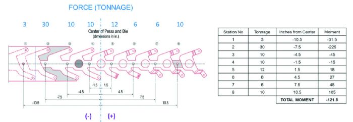
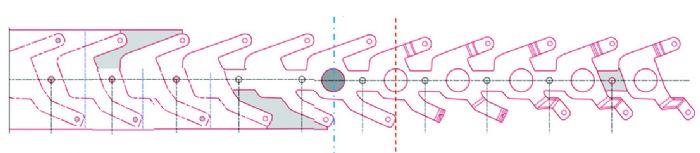 Now consider two progressive die strips (Figs. 1 and 2). At first glance, the eight-station layout in Fig. 1 appears to be the best choice. Fewer working stations mean a less-costly die, and elimination of idle stations provides a shorter die length that may allow the die to run in a smaller press. However, when calculating the tipping moments for each die station, the die in Fig. 1 produces a -121.5 in.-ton moment. The negative value indicates the center of load residing to the left of the die centerline. These tipping forces can compromise part quality and die life, and in the worst-case scenario, exceed press capacity. Conversely, the revised 10-station layout in Fig. 2 produces a total moment approaching zero, but at a higher tooling cost.

 Webinar