Die Alignment
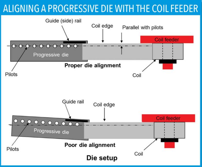 For progressive dies, ensure that the centerline of the die’s pilots run parallel to the coil-feed direction. Also ensure that you align the coil edge with the die’s side rail. If these items are set up incorrectly, you may not be able to feed the die smoothly (Fig. 2).
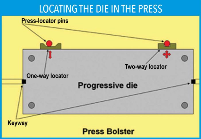
There are several ways to ensure proper die alignment. One is to key the die to the bolster plate. Keyways are precise, square cutouts machined into both ends of the lower-die shoe and the bolster plate. Small blocks of precisely machined steel called “keys” are fit into both the die and bolster, aligning the die. Other methods include using positive stops, or locator pins. This method simplifies and expedites die-setup time. Setup technicians simply load the tooling into the press with a fork truck or die cart, and push the die up to the locator pins until it stops. One pin locates the die right to left and front to back (two-way locator) while the other pins locate it front to back (Fig. 3). Regardless of the method used, make sure that the die sits parallel to the coil feeder.
Lowering Press Ram
 Before lowering the press ram, make sure that the shut height is slightly greater than the thickness or the final shut height of the tool. Don’t set the press’s shut height to the die’s final or finished shut height. Numerous computer-operated press systems will automatically set the press’s final shut height. However, keep in mind that a die’s finished shut height is calibrated with the die fully loaded with sheet metal.
Most dies have two or four setup blocks, also called stop blocks. These precision-ground blocks give the die-setup technician a means for checking, calibrating and adjusting the press shut height. They also can be used to check ram parallelism.
The process of cutting and forming metal requires a great deal of tonnage. Often, this additional tonnage will cause the press to deflect and open, especially when using an older, worn press. If the press’s shut height is set to the finished die height without having the die fully loaded, the additional tonnage will be applied to the setup blocks. Excessive force on the blocks will crush them into the surface of the die sets.
A crushed, deformed stop block is useless for calibration. If you can feel “footprints,” or steps in the die shoes where the stop blocks have been hitting, chances are that you no longer can use them to calibrate the tool’s shut height. Very simply, stay 0.020 in. or more off of the stop blocks during the initial setup. Final shut-height calibration can be adjusted later, after the die is fully loaded.
Clamping Procedures
 With the die nearly closed and all guide pins fully engaged, fasten all bolts and clamps. This process often is referred to as “floating the die in.”
Double-check the fasteners to ensure that all of them are tight. Don’t make assumptions. Use all of the clamping slots provided. When using toe clamps, ensure that the clamping pressure is applied to the die shoe and not to the leverage block. This can be done by positioning the leverage blocks slightly higher than the top of the die shoes. Don’t use numerous blocks to create clamping, or leverage, blocks. If using hydraulic clamps, ensure that they are working properly.
Secondary Shut Height Calibration
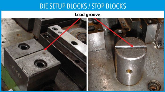
Most setup blocks have a precision-ground groove machined into them, to a depth of 0.030 to 0.050 in. (Fig. 4).
Regardless of the setup block’s depth, the groove should be at uniform depth for all. A small piece of solder or lead is placed in the groove of the blocks and the press is cycled. Assuming that the blocks have not been crushed, the lead thickness can be measured easily. Calibrate most dies for shut height when the die is 0.001-0.002 in. away from hitting the setup blocks to prevent block damage. For instance, if the lead measures 0.067 in. and the groove in the setup block is 0.050 in. deep, this means that you must lower the press ram 0.015 in. This setting will keep the die 0.002 in. from the blocks. Keep in mind that this is only a secondary procedure; final shut-height calibration must take place with the die fully loaded.
Ignore At Your Own Risk
Don’t take die alignment and clamping for granted. They are critical parts of the die setup procedure. All it takes is one mistake and—kaboom—you’re out of business.
Until next time … Best of luck! Art MF
Avoiding the Seven Deadly Sins of Stamping: Part 1
Avoiding the 7 Deadly Sins of Stamping: Part 2—Out-of-Sequence Timing
Avoiding the 7 Deadly Sins of Stamping: Part 4
Avoiding the 7 Deadly Sins of Stamping: Part 5 Metal-Flow Principles for Square Parts
Industry-Related Terms: Bed,
Die,
Draw,
Edge,
Forming,
Plate,
Ram,
Run,
Scrap,
Shut Height,
Stripper,
Surface,
Thickness,
Transfer,
FormingView Glossary of Metalforming Terms
See also: Dieology LLC
Technologies: Tooling


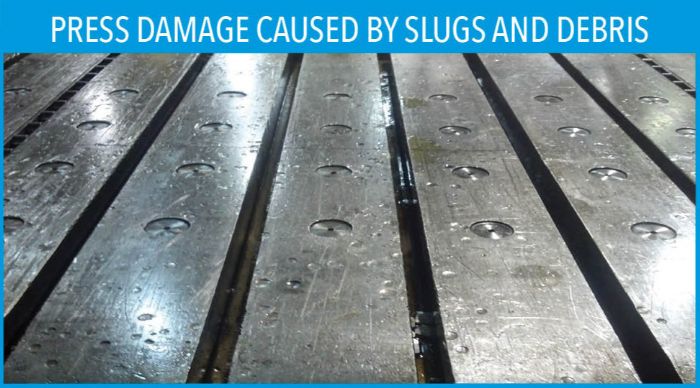 During the die-threading process, startup scrap is generated and, if left in the die, may double-feed sheet metal into the tool. Often during setup, pressure, stripper and draw pads are half-loaded and unbalanced. The list goes on and on.