Brad Kuvin Brad Kuvin
Editorial Director

Die Springs—Coil vs. Gas; Best Practices

February 1, 2017
0
Comments


While the gas-spring industry has done a bang-up job earning market share from coil-spring suppliers, experts interviewed for this article agree that you can’t paint a broad picture when it comes to selecting the right solution for metalforming dies. Where can stampers still use coil springs? We asked Ray Osborne, vice president of sales at Moeller Precision Tool, Wixom, MI.

Considering a 2-in. stroke, the die designer would need a coil spring with a free length of 8 in., compared to a 5.12-in. gas spring. Also, it would require four coil springs, fully compressed 2 in., to equal the force of one 25-mm nitrogen-gas spring.
“Applications where you don’t need nitrogen,” Osborne says, “may include simpler dies where you don’t have a lot of stripper-pad travel; flat parts that don’t have a lot of form in them; high-speed dies; and tools requiring short strokes such as those used to stamp electronic parts.”

On the flip side, Jim Glynn, president gas-spring supplier Special Springs, LLC, Canton, MI, warns against painting the die-spring picture with a broad brush, noting that the majority of dies now are designed with gas springs.

“Coil springs exhibit some limitations, due to the greater force required to form or strip,” Glynn says. “This becomes increasingly important as more metalformers begin to fabricate higher-strength materials. You don’t always have room in the die to use as many coil springs as might be needed. Gas springs become the default solution for these jobs. For shorter runs and in areas where you don’t need as much force for stripping or forming, you might be able to get away with coil springs, provided they are preloaded, and properly designed and installed.”

Coil-Spring Commandments

“With the continuing, immense pressure to reduce die cost,” explains Osborne, “it often is bewildering to see the prevalence of nitrogen-gas cylinders in the marketplace. I often see elaborate gas-spring installations where they are not necessarily warranted.”

In response, Glynn notes that “gas springs generally comprise less than 4 percent of total die cost.”

When metalformers do opt to use coil springs, Osborne offers this laundry list of best practices:

• Always incorporate preload (a minimum of 5 percent of free length), achieved by correctly specifying the spool/keeper lengths used in securing the stripper pad, lifter rail or other moving element being considered.

 
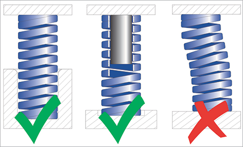
Among Osborn’s recommended practices for using coil die springs: Follow recommended procedures for guiding. “Guiding on the spring ID (center illustration) is preferred,” Osborne says, “even though in most applications stampers wind up guiding on the OD (left). But by investing a little more upfront to guide on the ID, you create less contact area and minimize wear.
• Ensure flatness (to within 3 percent) and perpendicularity of the contacting surfaces, to within 1 deg. or less.

• Follow recommended guiding practices. “Guiding on the spring ID is preferred when possible,” Osborne says, “even though in most applications stampers wind up guiding on the OD. But by investing a little more upfront to guide on the ID, you create less potential contact area and minimize wear.”

• Reduce or eliminate the possibility of scrap material or other foreign objects becoming trapped between the coils, by adding spring cans or other guarding to the setup.

• Never cut springs to length. Always purchase and install the correct spring for the application. “Cobbling springs to force-fit an application is penny-wise and pound-foolish," says Osborne.

• Replace broken springs immediately, and always replace springs as a complete set.

• Be mindful of increases in deflection due to shut-height changes that result from routine die sharpening.

• Be mindful of series versus parallel arrangements. The resulting load calculations are very different.

• When inspecting springs to gauge their condition, look for worn paint or shiny surfaces, indicators that surfaces are rubbing. “Surfaces should be free of striations or cracks,” Osborne says. “Visually inspect them every time the die goes in for sharpening or general maintenance. And any time the stripper pad is removed and the springs can readily be removed, give them a rattle—if they’re cracked you will hear or feel it.”

Spring Selection—Shoot for Two out of Three

When selecting the right coil spring for the job at hand, Osborne offers a simple and often-cited anecdote, along the lines of ‘good quality, low price and fast delivery.’

“Typically a metalformer can get any two of these three,” he says. “And with coil springs it’s the same—where the three variables are force, deflection and spring life, and you can only get two of the three. For example, if you need a lot of force over a large deflection, don't expect long life. In this case, nitrogen-gas springs might make sense.”

In gas-spring applications requiring a lot of die lube, be sure to protect the springs from contamination by using protective rod covers (shown here) or wipers. “Contamination is a leading cause of spring failure,” says Special Springs’ Jim Glynn.
An exception to this rule, says Osborne: springs used for misfeed protection within, say, an in-die tapping device. “You need high force and long travel,” he says, “and you don’t care about life because the springs operate statically—in a healthy application they never cycle. So, even though they are under considerable preload and expected to travel a long distance, they rarely if ever actuate, so their life will not be a consideration.”

Lastly, Osborne issues a warning to manufacturers looking to use die springs for non-die or mold applications, which he says is becoming more common. Here the user needs to fully understand spring rate, or the spring constant, that governs the force-deflection curve.

“Typically, spring manufacturers provide a spring-rate tolerance of ±10 percent,” Osborne says. “This works fine for dies and molds, but in non-tooling applications it may not suffice; the application might require a tighter tolerance on spring rate. For these applications, many manufacturers offer (for a premium) springs with the constant controlled to within ±3 to 5 percent.”

Gas Springs: Heed the End Force

When it comes to specifying gas springs, Glynn notes that most are rated for a maximum speed of 1.8 m/sec., and, depending on press stroke, gas springs can run at press rates to 200 strokes/min.—depending, of course, on the amount of stroke.

“With just a shorter stroke, less than 12 mm,” he says, “you can run with gas springs at faster press speeds. But, with more than an inch of stroke, press speed can be limited to around 100 strokes/min.—the limiting factor being the heat caused from the friction and pressure rise in the springs. When selecting the right gas spring for the application, the stamper must carefully consider the force profile needed for the entire spectrum of forming, piercing and stripping requirements.

“Also important is understanding where you need the force,” Glynn continues. “Gas springs provide force on contact, and the force can increase as much as 50 percent as the piston rod compresses. If the stripping or forming force is calculated for the end of the stroke, then the die designer may be able to use fewer springs and reduce die cost, since the end-of-stroke force can be significantly greater than the initial contact force.”

While most gas-spring manufacturers offer a variety of sizes in terms of force, diameter and overall length, the industry, Glynn says, is settling in on ISO and VDI (The Association of German Engineer) standard gas springs. Most major gas-spring manufacturers comply with these standards, which allows the springs to be interchangeable and helping stampers reduce downtime and cost.

Glynn warns, however, that “when repairing gas springs, use the repair kit specified by the manufacturer—these are not interchangeable. And, as a general rule, I recommend that shops only repair gas springs with a body diameter larger than 50 mm.”

Sharing Other Best Practices

Glynn stresses that die designers should specify gas springs so that only a maximum of 90 percent of rated spring stroke is used. “The less stroke the better,” he says, “to reduce friction and pressure and prolong spring life.”

Also sound practice: Ensure that the spring sits on a flat surface, with the rod perpendicular to the striking surface or pad. This is critical to avoid side loading.

“To optimize spring life,” Glynn adds, “attach springs using a mount or the tapped holes in the bottom of the springs, so they’re not loose in the die. If the springs aren’t fastened, metal contaminants or debris can wedge their way underneath the springs, which would then create a misaligned or angled spring and lead to side loading.”

If stampers do elect to just drop the springs into the pockets machined into the die, Glynn suggests that they design the pockets with clearance based on the manufacturer’s recommendations, to minimize the chance of contamination. And, in applications requiring a lot of die lube, use springs with protective rod covers or wipers to guard against contamination, “a leading cause of spring failure,” he says.

Connecting Gas Springs to Control, Adjust Force

Hosed or linked nitrogen systems provide the most flexibility for metalforming. “Gas springs can be linked together,” Glynn explains, “with a series of high-pressure hoses, or via a 1-in. manifold plate. This system is the cleanest and, I believe, the most reliable.”

To take this a step further, designers can add pressure switches (electronic pressure monitors) to the system, Glynn says, allowing the stamper to set parameters based on the pressure profile that optimizes part quality. And, should pressure fall below a certain level, due to a leak in the system, it signals the press to stop.

A great example of the benefits of connecting gas springs via a manifold setup, says Osborne: in-die tapping, where considerable stripper travel is needed to locate and control the part during the tapping operation.

“In some cases,” Osborne notes, “the tapping unit is mounted in the upper die, within the stripper. It is critical that those gas springs be linked together to ensure uniform balance in the stripper pad. Otherwise, should one or two gas springs go flat in one corner, the stripper won’t hold down firmly in that corner, which can wreak havoc with the tapping unit and lead to broken taps and cause damage to the unit. It’s mandatory that stampers use a manifold when using nitrogen for in-die tapping operations.”

A Critical Note About Safety

Lastly, Glynn notes a relatively new focus on safe use of gas springs, which came to light in November 2015 when VDI added new safety guidelines to its VDI 3003 Standard, “Nitrogen Gas Springs in Large Stamping and Forming Dies.” These guidelines arose from the fact that gas springs, under high pressure require that safety be top of mind.

“Because these springs contain a lot of pressure,” Glynn says, “which can range from 2000 to more than 4000 psi during compression, they’re nothing to fool around with. Because of this, we and other manufacturers have focused on developing new safety features, following the VDI guidelines. These fall into three categories: protection from over-stroke and over-pressure, and protection from return stroke without counterforce.”

Here’s the language contained in the VDI standard:

• Return stroke of nitrogen-gas spring without counterforce

Do not use gas springs in such a way that the piston rod is released freely from its compressed position. This can be caused by a jammed pressure pad or cam. As a result, the nitrogen gas spring exceeds the permitted speed during the return stroke, causing the piston rod to slam unchecked onto bushing. This can damage the nitrogen-gas spring or cause it to fail (high-speed return of the rod). To avoid this, use only nitrogen-gas springs that are designed to vent gas, thereby depressurizing the spring.

• Over-stroke

Over-stroke occurs when the piston rod is pushed deeper into the gas-spring body than the nominal stroke length. This can damage the gas spring. Use only gas springs that are designed to vent the gas completely to atmosphere in a controlled manner in the event of over-stroke.

• Over-pressure

Gas springs can break if the pressure inside rises due to fluid penetration or incorrect charging above the permitted limit. If fluids are used, it is advisable to ensure that gas springs have over-pressure protection. When the over-pressure-protection system is triggered, the gas is vented safely. MF

Industry-Related Terms: Cam, Case, Corner, Die, Form, Forming, Gauge, Lines, Nominal, Penetration, Perpendicularity, Piercing, Plate, Run, Scrap, Spectrum, Stripper, Stripping, Stroke, Surface, Tapping, Tolerance
View Glossary of Metalforming Terms


See also: Moeller Precision Tool

Technologies: Tooling

Comments

Must be logged in to post a comment.
There are no comments posted.

Subscribe to the Newsletter

Start receiving newsletters.