Deciphering Weld Symbols, Part 2: Groove Welds
September 30, 2020Comments
We review common welding symbols and their meaning, with the focus in this article on groove welds.
 We review common welding symbols and their meaning, with the focus in this article on groove welds. Part 1, presented in the August issue of MetalForming, covered welding-symbol structure and provided an overview of symbols for fillet welds as well as for plug and slot welds. Welders commonly perform groove welds to make edge-to-edge joints, although groove welds also are used for corner joints, T joints and joints between curved and flat pieces.
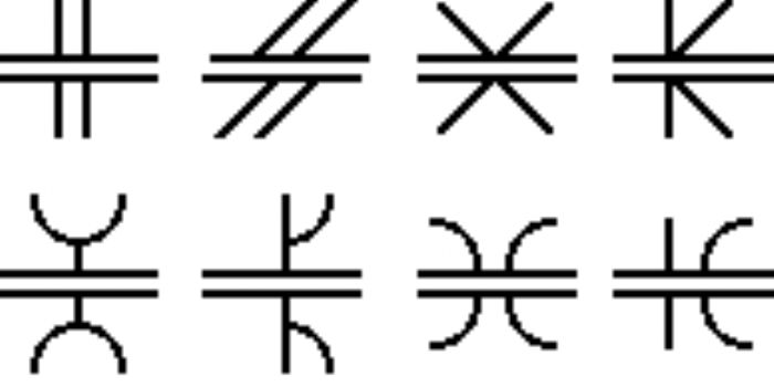
 The variety of groove-weld symbols (Fig. 1) suggests many ways to make a groove weld, the differences depending primarily on the geometry of the parts to be joined and the preparation of their edges. Performing a groove weld consists of depositing weld metal within the groove, where it penetrates and fuses with the base metal to form the joint. (The drawings in this article generally do not show the penetration of the weld metal. Note its importance, however, as the degree of penetration is crucial in determining weld quality.)
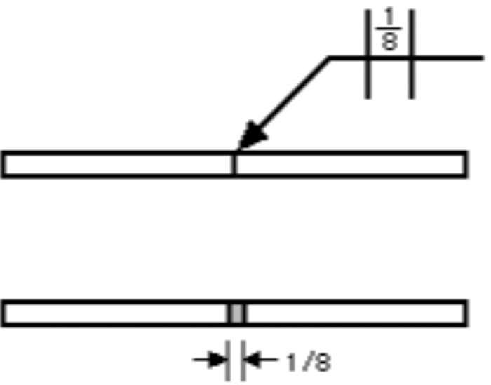
Square Groove
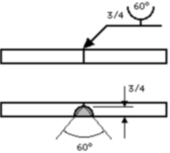
In a square-groove weld, the groove is created by either a tight fit or a slight separation of the edges. The weld symbol indicates the amount of separation (Fig. 2).
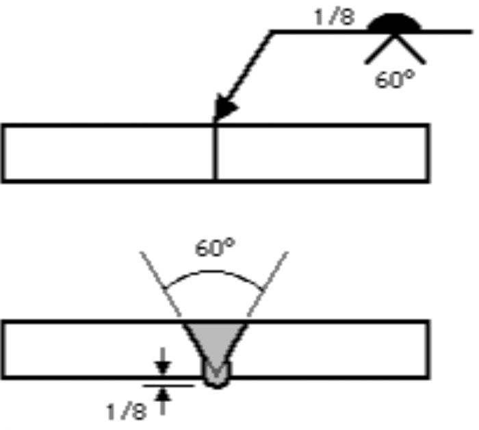
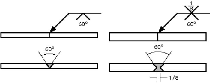
V Groove
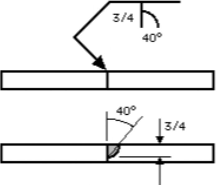
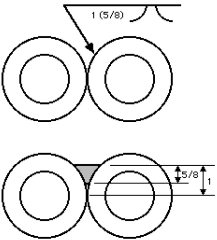
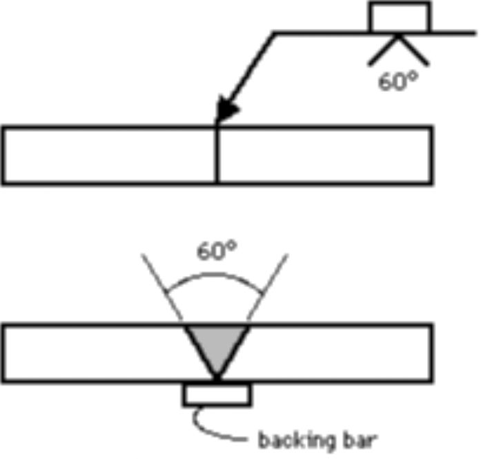
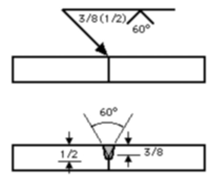 With V-groove welds, the edges of both pieces are chamfered, either singly or doubly, to create the groove. The weld symbol provides the angle of the V, as well as the separation at the root, if any (Fig. 3). If the depth of the V does not reach the full thickness of the workpiece, or half the thickness in the case of a double V, the depth is noted to the left of the weld symbol. Should weld penetration be greater than the depth of the groove, the depth of the effective throat is provided in parentheses after the depth of the V (Fig. 4).
Bevel Groove
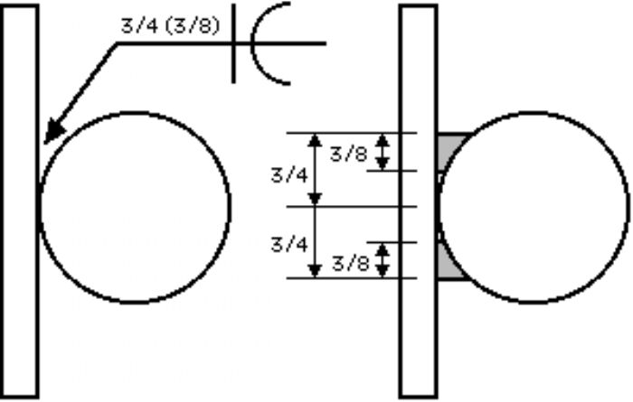
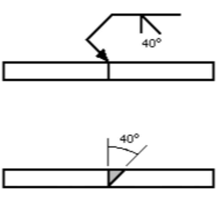 When performing a bevel-groove weld, the edge of one of the workpieces is chamfered, with the other left square. The bevel symbol's perpendicular line always is drawn on the left side, regardless of weld orientation. The arrow points toward the piece that is to be chamfered, emphasized by a break in the arrow line (Fig. 5). The break is not necessary if the designer has no preference as to which piece receives the edge treatment or if the piece to receive the treatment should be obvious to a qualified welder. Angle and depth of edge treatment, effective throat and separation at the root are described using the methods discussed in the V-groove section.