After adding Logopress3, Christopherson and his team had another major problem to tackle: the amount of time spent on CAM programming.
“At the time we had four programmers along with three CNC mills and two CNC lathes.” Christopherson recalls. “Back then, 3D milling entailed only about three to four percent of our work and even so, 2.5-axis programming always was our big bottleneck.”
Trueline added SolidWorks-based CAMWorks software, which is both feature-based (with feature recognition) and rules-based. The team found that it could easily customize Logopress3 to integrate with the new CAM software to automate 2.5-axis CNC programming.
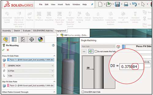
For example, when inserting a catalog component, Logopress3 automatically and simultaneously cuts all holes in all the related plates for this component. The hole sizes that it cuts are user-definable within the software’s spreadsheets. Trueline has developed predefined decimal values and added instructions for these values, which allow the rules-based CAM software to automatically determine what steps to take to machine each hole. Today, the company employs one programmer for four CNC mills and three CNC lathes. Should this programmer fall behind, one or more die designers easily can assist with programming. Automation inherent in the software makes this possible, along with the fact that the CAM software runs inside of the same SolidWorks interface as the die-design software.
Trueline recently added contract-molding services and found that mold designers could make good use of Logopress3 for tasks common to both die and mold design. Nowhere is this more evident than in the integration of the company’s CAM software and die-design software. Today, reports Christopherson, the entire group of die designers, mold designers and their CNC programmer work together as a cohesive team due in large part to the organization that the software provides.
Unique Solution for Precision-Stamped Link
|
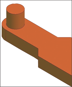
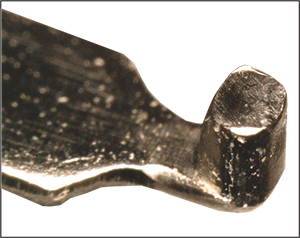
| Fig. 1—A two-piece part design presented numerous manufacturability issues. Devising a new solution necessitated the use of simulation software to prove it out. |
Penn United Technologies, Cabot, PA, specializes in metal stamping, carbide manufacturing and precision tool and die design. A recent customer approached the company with an opportunity to manufacture a precision-stamped link, to be made from 0.022-in.-thick Type 301 quarter-hard stainless steel. The link, a two-piece design, would join a flat beam and cylindrical stud (Fig. 1). Potential joining solutions included press-fit and laser welding.
Engineers quickly identified a number of concerns during design-for-manufacturability reviews. The cross-sectional profile around the hole was quite thin relative to sheet thickness. Resulting cut- and break-edge conditions likely would be unsuitable for press-fit assembly, and customer design constraints did not allow for larger profiles, which would have resolved these concerns. As a result, laser welding would be required, driving up capital and per-piece costs.
Limited by these constraints, Penn United staff developed an unconventional solution: forming a round stud directly from the flat base stock. With no precedence for such a design, the solution presented several concerns. Type 301 stainless steel has a fairly high work-hardening rate, so large deformation may lead to cracking. Starting with quarter-hard material, to meet customer strength requirements, only increases this risk. Also of concern: how round, uniform and filled the stud would be at various heights.
|
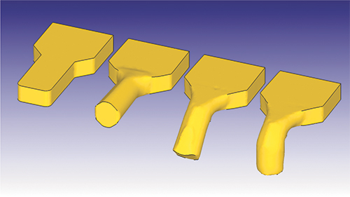
| Fig. 2—Positive simulation results for a new part design convinced designers and the customer that development and testing could move forward. |
Needing a way to evaluate the unique concept and maximize its chance of success, Penn United turned to the Deform system for bulk-metal-forming process simulation, developed by Scientific Forming Technologies Corp., Columbus, OH. The team modeled the proposed progressive-stamping process in the Deform-3D multiple-operation environment. Stud formation would take place across three forming operations, and the process design incorporated tool movements in three directions.
Simulations allowed Penn United to predict how blank geometry and tooling design impacted the finished part. Toolmakers optimized die fill, once the customer identified allowable underfill areas of the part. Simulation also allowed Penn United to predict the risk of cracking using the damage-state variable. Engineers knew the material’s critical damage value, at which cracking and other defects would be likely, based on historical data. Thus, they maintained a comfortable factor of safety and minimized the risk of cracking.
 |
| Fig. 3—A completed part confirms simulation predictions and leads to long-term successful part production. |
In addition to technical benefits, simulation output allowed Penn United to clearly and concisely communicate results to its customer, with process design established scientifically, rather than through a gut feel. The customer analyzed this feedback, particularly the anticipated die fill, to determine viability of the solution.
Positive Deform simulation results (Fig. 2) convinced the customer to move forward with development and testing. Penn United manufactured single-hit tooling and produced a small batch of prototypes, and the final parts (Fig. 3) correlated well with simulation predictions.
Subsequent product testing of the link revealed the customer’s desire for slightly more die fill, so further refinement of the stamping process accommodated this change. Toolmakers used simulations and tests on hard tooling to optimize the updated design, which now included a fourth forming operation, and subsequently manufactured a progressive-stamping die for high-volume production. Penn United, reporting long-term success in running this job, credits Deform for developing and proving out the company’s ‘outside-the-box’ concept. MF
Industry-Related Terms: Blank,
Cam,
CNC (Computer Numerical Control),
Die,
Forming,
Hard Tooling,
Laser Welding,
LASER,
Manufacturability,
Stainless Steel,
ThicknessView Glossary of Metalforming Terms
See also: Scientific Forming Technologies Corp., Accurate Die Design Software, Inc., LOGOPRESS
Technologies: Software


 Webinar