 When running thin metals with a total thickness variance of 0.002 in., the shut-height difference may not be much of an issue. However, when running 0.100-in.-thick hot-rolled steel (per ASTM A1011), expect a thickness variance of as much as 0.016 in. In this case, bringing the ram down onto the set blocks results in significant tonnage increases, which may greatly exceed the calculated tonnage for that die. A press without a tonnage monitor provides no way to know if press capacity is being exceeded. Even for material procured to half-standard tolerance (0.008-in. variance), this still represents a considerable amount of overhitting on the die, especially when forming stainless steels and higher-strength steel grades.
Solder Check Methods
Today, many dies incorporate a solder-check feature—a machined groove in the top of the set block—to aid setup personnel in making fine shut-height adjustments. The die setter places a small length of 1⁄8-in.-dia. solder in the groove, strokes the press with all of the die stations loaded, removes the flattened solder from the set block grooves and measures its thickness. Some companies simply require the flattened solder thickness to measure a couple of thousandths inches greater than the groove depth to assure that the press does not generate false tonnage by hitting on top of the set blocks. However, this does not account for any variance in stock thickness.
 Unfortunately, no industry standard describes how to establish the set-block height, the depth of the solder-check groove or procedural steps for making final shut-height adjustments. Fig. 2 provides one option that allows a die setter to set the die shut height relative to material thickness.
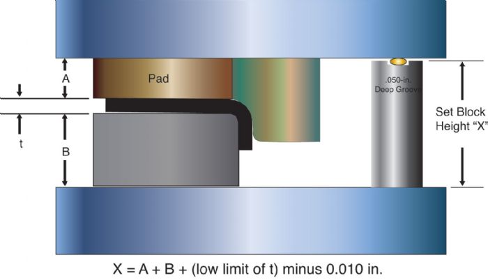
The inside shut height for this die is the sum of the pad thickness (A), die thickness (B) and the low limit of material thickness (t). The height of the set block should be less than the calculated shut-height dimension to assure that the set blocks do not contact the upper die shoe (eliminating false-tonnage readings). This height reduction is arbitrary, but can range from 0.002 to 0.020 in.
I used 0.010 in. for the height reduction in Fig. 2, making the formula for the set block height:
A + B + (low limit of t) minus 0.010 in.
The groove depth, also arbitrary, typically ranges from 0.040 to 0.060 in. In this example I use 0.050 in.
Establishing the Shut Height
With the die stations fully loaded, place solder in the set-block grooves, stroke the press and measure the solder thickness. With the material thickness at its low limit, the flattened solder thickness should equal 0.060 in. As material thickness increases, so should the thickness of the flattened solder. For example, if material thickness measures 0.008 in. above the low limit, then the flattened solder should measure 0.068 in. with a correctly set shut height.
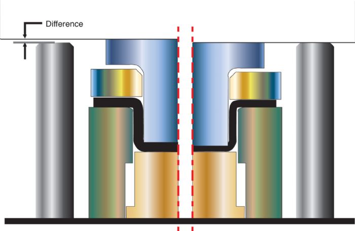
For dies with more than one set block, comparing solder measurements with the other set blocks can indicate an out-of-parallel condition in the die. This condition could be caused by any number of issues including improper die timing, excessive die-tipping moments, a bent or out-of-parallel ram or other press-related issues.
Springback Compensation
With a correct die shut height for the material thickness in the die, personnel have no reason to adjust the shut height until the material thickness changes. Far too often the die shut height is altered to compensate for timing issues inside of the die, such as a stencil hitting too hard or too light, or a sprung-open or overbent flange. After correctly setting the die shut height, never adjust the ram up or down to increase or decrease pressure for stencils and forms. These timing issues must be corrected by means of shimming.
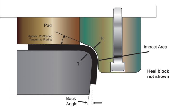
Fig. 3 shows a bending station with a form block (or an insert) designed for simple removal in the press to facilitate adjustments. Now, forming pressure can be increased or decreased to adjust springback by adding or removing shims under the punch.
The correct die shut height and internal die timing helps to ensure quality production parts, improved press performance and less die damage. MF
Industry-Related Terms: Bending,
Case,
Die,
Dimension,
Flange,
Form,
Forming,
Ram,
Shut Height,
Stroke,
Surface,
Thickness,
Tolerance,
TransferView Glossary of Metalforming Terms Technologies: Tooling


 When dies require parallels, set blocks must be positioned directly over parallels to support any excess force applied to the set blocks by the upper die. This often is referred to as ‘over-hitting the die.’ Parallels under the set blocks reduce the likelihood of a permanently bent or distorted die shoe.
 Video
Video