Forming of Heat Shields for the Automotive Industry
June 8, 2022Comments
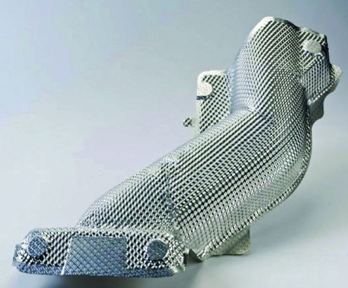
Internal combustion engines, albeit losing their once top position in the automotive industry, generate excessive heat—around the engine and its exhaust components. If not properly insulated, high temperatures may cause thermal damage to body components, electronics and internal trim. Typically, an embossed and formed heat shield (Fig. 1) is used for protecting the rest of the car from excessive heat.
 Most heat shields are stamped from 0.3 to 0.5-mm, 1000- or 3000-series aluminum; when double sheets are used, sheet thickness may be as low as 0.2 mm. 1050-O or 3004-O materials are delivered as coil, then roll-embossed to have hexagonal or hemispherical bulges. Embossing adds stiffness to the extremely thin sheet, while also increasing surface area and reflectivity to improve heat dissipation and reflectivity. However, embossing also hardens the sheet, possibly detrimental to the second forming operation. Once an O-temper sheet is embossed, it should be renamed as H114.The ratio of bulge height to diameter affects the amount of thinning and hardening that occurs. Embossing can improve formability, but only if the geometry is optimized.
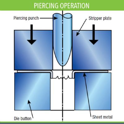
 During the second metal forming step, blanks are cut from the embossed coil. Here, cut-to-length rectangular blanks can be used to reduce costs; a blanking die may be required for some geometries. The blanks then transfer to a forming press. To reduce costs, crash forming—requiring only a punch and a die—is preferred, rather than draw forming, which requires a blankholder.
Challenges During Heat-Shield Manufacturing
Wrinkles nearly always appear when crash forming thin sheet. However, because heat shields typically are unexposed and their primary duty is not visual but thermal, automakers accept some wrinkles. The critical issue: The height of the wrinkles must not cause any problems during assembly.
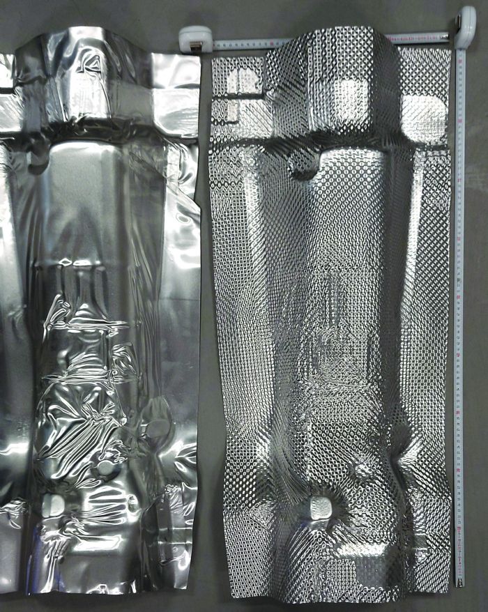
During sheet metal forming, wrinkles occur due to low stiffness of the sheet and compressive stresses during forming. Luckily, embossing increases sheet stiffness and, therefore, helps to reduce wrinkling (Fig. 2). If wrinkles cause problems during assembly, draw forming may be required rather than crash forming, using either a force-controlled blankholder or local pads, depending on part geometry.
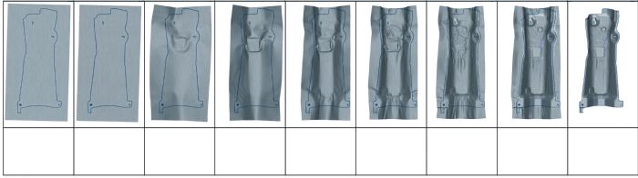 To investigate simulation of heat-shield production, we modeled the roll-embossing and crash-forming processes in two commercially available simulation programs. We used an initial rectangular blank cut from 0.5-mm-thick 1050-O aluminum.
 Webinar