


Off-Center Loading
August 27, 2020Comments
Recent columns addressed horizontal forces (side thrust) in dies and provided methods to manage them. Dies generate other types of forces,―particularly progressive and transfer dies―that can cause the press slide (ram) to tip to one side, resulting in an out-of-parallel condition inside of the die. These forces, called tipping-moments, produce off-center loads that if not properly managed can affect part quality and damage tooling.
 Arbitrarily positioning the centerline of a progressive or transfer die with the centerline of the press slide ignores the fact that when two or more die stations perform their work, the forces may not occur simultaneously or be equal in magnitude across all of the working stations. When forces are not distributed evenly across the press slide, the press slide will tip and move laterally in the direction of the greatest force. If this movement occurs while punches are engaged with other die components, excessive wear or die damage may occur. Damage and wear increases maintenance costs and compromises dimensional consistency of the stampings being produced. When off-center loads exceed press capacity, wear and damage to the press also can occur.
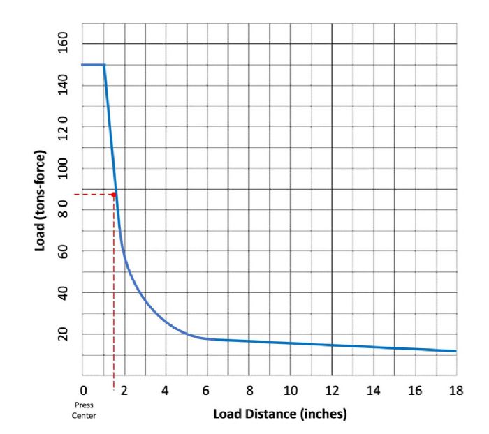
Manufacturers design stamping presses to handle some amount of off-center loading. Importantly, the maximum load is not a singular value, but rather a continuum of values relative to the distance from the press centerline. Fig. 1 depicts limits in the left-to-right direction for a hypothetical press. Front-to-back loading would result in a similar graph, but because many progressive and transfer dies produce reasonably balanced loads in the front-to-back direction, for simplicity we will consider only left-to-right loading.
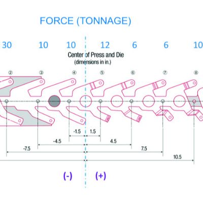
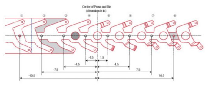 To calculate the tipping moments produced by a die, we multiply the cutting and forming forces by their distances from the center of the press. Using the center of the press as the origin (zero), distances to the left have negative values, with positive values for distances to the right, as in a number line. In a perfect world the sum of all of the moments would total zero, indicating that the center of the load is balanced at the center of the press.
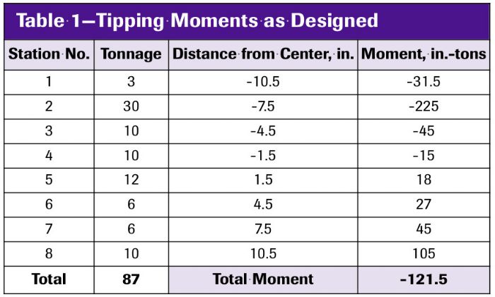 Thus, the center of the 87-ton load locates 1.4 in. to the left (negative value) of the press centerline. To center the load, shift the die 1.4 in. to the right. The goal here is to position the center of the load, not the center of the die,―on the centerline of the press slide.
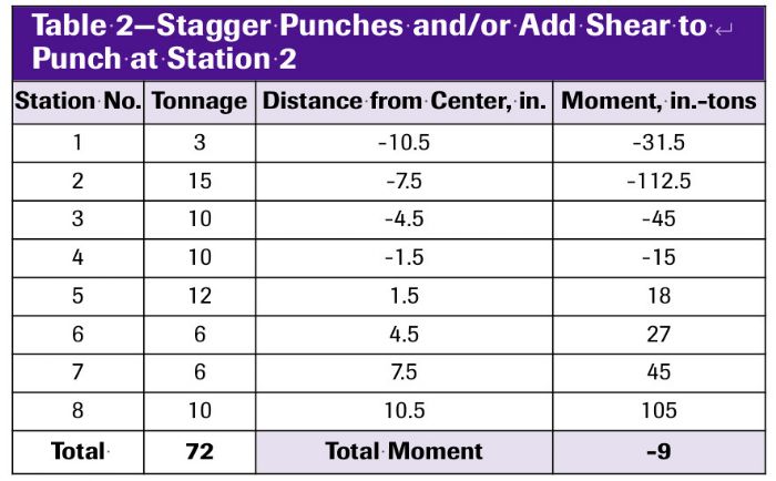 Another option: Strategically apply cutting shear and/or stagger select cutting punches. For example, we could reduce the cutting force in station number two by nearly 50 percent by staggering the punches by approximately one-half of sheet metal thickness or by adding shear. Table 2 shows the resulting reduction in forces and tipping moments.

 Webinar