Shaving Operations
January 20, 2023Comments
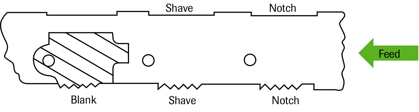
Stamping applications requiring square-cut edges and close dimensional tolerances often make good candidates for shaving. Shave operations most commonly associate with punched openings such as round holes, but free-edge features also can be shaved.
Hole-Shaving Parameters
 Generally, the amount of material to be removed by shaving totals about 10 percent of sheet thickness for most applications. This provides good edge conditions and allows enough material in the “scrap ring” for slug retention—an important point as slug retention represents a common problem with shaving operations.
 The amount of material removed by shaving can relate to the size of the cut-edge fracture zone (die break). Diemakers and tool engineers sometimes mistakenly believe that reducing the length of the fracture zone—by reducing punch-to-die clearance in the punching station—will help reduce shaving-related problems by reducing the amount of material being shaved. Unfortunately, this approach usually causes more problems than it solves.
Reducing punch-to-die cutting clearance produces a larger shear band and a correspondingly smaller fracture zone. However, a larger shear band also produces a larger cold-worked zone that makes shaving more difficult due to the increase in cutting force, friction and process heat, leading to punch fatigue, chipping and increased punch wear. The burr resulting from tighter punching clearances also interferes with accurate part positioning over the shave-die opening. And, removing the burr by shaving alone proves difficult, as a smaller scrap-ring web results, which hampers scrap shedding.
Typically, the proper punch-to-die clearance in the punching station is the largest clearance that produces a high-quality shear band and a clean break edge without producing a burr. These engineered clearances—as much as 10 to 15 percent/side, depending on the material thickness and type—optimize tool life and minimize work hardening inside of the hole.
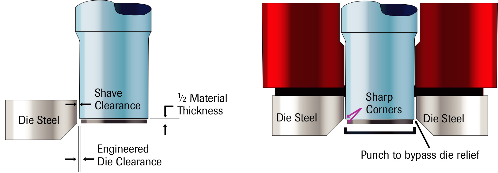 Conversely, shave clearances will be very tight, generally 1 to 1.5 percent of sheet thickness per side. Excess clearance in the shave station results in shearing and refracturing of the hole. Small cutting clearances in the shave station result in a shaved edge measuring slightly less than 100 percent of material thickness. Edges that must be sheared to 100 percent of material thickness require special processes, such as fine blanking.
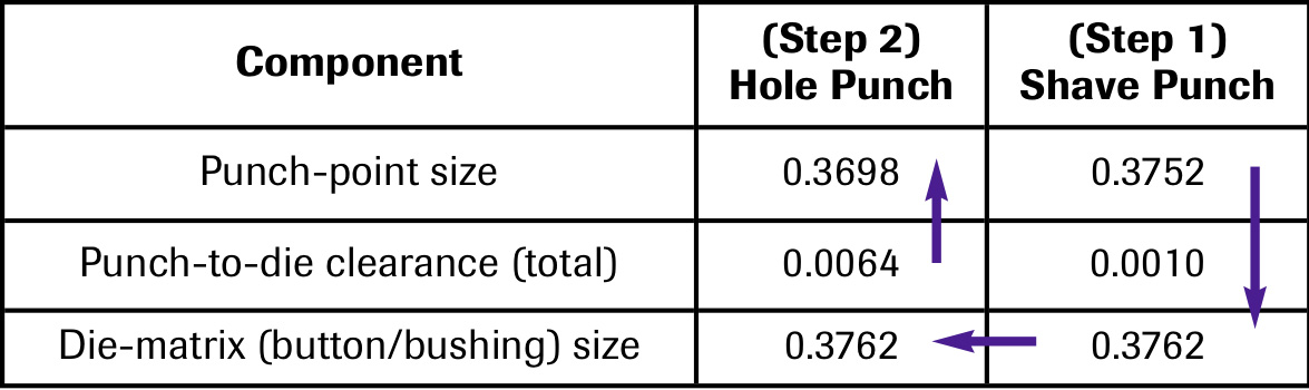
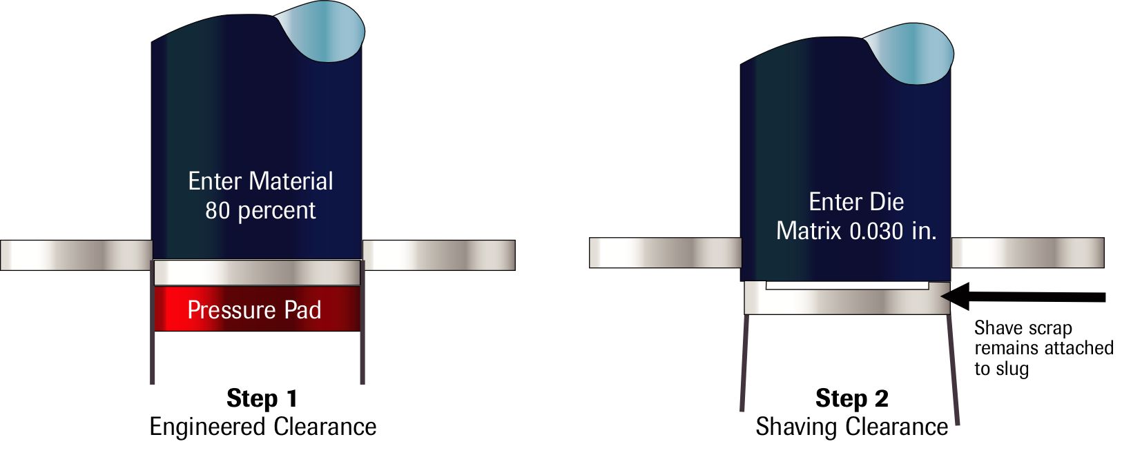 Very close tolerances, or when shaving thick materials with pronounced die break or taper, may require more than one shaving operation. When applications require two shave steps, the amount of material shaved in the second step should total one-half that of the first step. As an example, for a total shaving of 0.009 in. of material, remove 0.006 in. via the first shave punch and 0.003 in. via the second.
 Webinar