Understanding Sensors & Error-Proofing, Part 1: Inductive Proximity Sensors
December 1, 2015Comments
This first in a series of articles will address the basic topics of how to properly select, install and protect inductive proximity sensors within tooling.
Hundreds, if not thousands, of metalforming companies, toolmakers and pressroom personnel have tried and failed to properly implement electronic sensors within their dies. The sensors are consequently deemed by many to be ineffective, too delicate, impossible to properly align with a target, unable to survive the harsh environments within a die, etc. But in great measure, these failures are due to simple misunderstandings regarding sensor location, mounting and protection. We must correct these misunderstandings to ensure ideal sensor performance.
Toolmakers worth their salt quickly acknowledge the precision with which tooling components are engineered, designed and located within dies, from manually fed, single-stroke types on through to automatic progressive and transfer dies. Every internal component has been carefully designed and placed with precision by toolmakers, and maintained with equal care by maintenance toolmakers during production cycles. Should not the same care be taken regarding selection and installation of electronic sensors to protect these valuable electronic investments? Where is it written that it is okay to crash and repair a die? What genius came up with the phrase, “Oh, that die can take a bad hit?” Who designs dies to take such a bad hit? I have yet, in 30-plus years of consulting with companies on die protection, to see an addendum or note or scribbled phrase on a given die-setup sheet, design drawing or a purchase order, specifying that a die crash is acceptable. Sensing Fields Explained
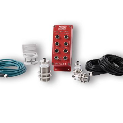
Inductive proximity sensors, the most commonly used electronic die-protection sensors, are available from numerous vendors and come in a variety of sizes and geometries. The vast amount of these sensors used for die protection have a sensing field that must be thoroughly understood in order for them to work properly, consistently and in many cases, for the life of the die. Many incorrectly refer to the sensing field as a magnetic field. If that were true, then how to account for their use with copper, brass and aluminum? No, it is not a magnetic field but rather an inductive field, radio field or, in shorthand, RF. Think of your car radio, where your favorite station has a particular frequency…say 100 MHz. That is the number to which you tune the radio. That particular radio station sends out an electromagnetic signal with cycling waveforms traveling in a repeatable pattern of 100 million cycles/sec., or Hz. Likewise, an inductive proximity sensor sends an RF signal, typically at or under 1 MHz. As with the radio station’s signal, the RF signal from the inductive proximity sensor is invisible. With the sensor on, nothing seems to emanate from its sensing surface, but the invisible RF field coming from the inductive proximity sensor is both water- and oilproof. Knowing the Sensor Field a Must
A toolmaker or machinist must understand the exact size of that sensor’s field so that a precise detection of the target within the die can be made, and that the sensor is located properly for that detection. Why? Because the size and shape of the inductive proximity sensor’s RF field typically differs for each type of tool steel and strip material in the shop. In other words, if an inductive proximity sensor works well in a particular die detecting a block made of D2 material, the very same sensor will have a completely different RF shape and range when paired with 4140 or A2 tool steels. Ditto for strip materials. If a given inductive proximity sensor works well detecting a target on a strip made of cold-rolled steel, the very same sensor will have a completely different reaction when tasked with detecting a target made from Type 303 stainless steel—even if the parts are exactly the same and the sensor is located at the very same detection distance. Some inductive proximity sensors are marketed as having the same sensing field for all materials. Be very careful when dealing with these types of sensors, as you need exacting proof that these claims ring true. Even slight variations in the shape and range of the RF field, in a sensor labeled as being insensitive to material types, can lead to, for example, undetected strip misfeeds.
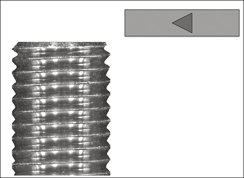
Fig. 1—When using a test bench to determine the sensing field, an inductive proximity sensor can mount vertically on a fixture, typically a height gauge where a customized insert holds the sensor in position. The target, ideally a small metallic coupon mimicking the material and shape of the item to be sensed in production, is moved slowly and accurately right to left into the invisible radio-field signal coming out of the top of the sensor.
<
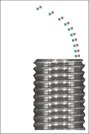
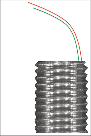
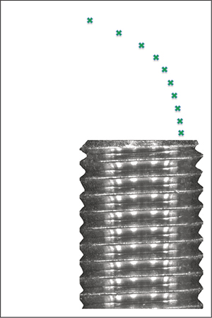
Fig. 2—The green marks indicate the various positions in space where the sensor detected the coupon.
Fig. 3—The OFF point—the location where left-to-right movement of the target coupon causes the sensor to turn off − is indicated in red. Note the definite gap between the target coupon turning on the sensor, marked in green, and turning it off.
Fig. 4—With the data obtained as shown in Fig. 3, a macro function in an Excel spreadsheet connects the ON and OFF points into lines. This sensing-area fish pattern is three-dimensional.
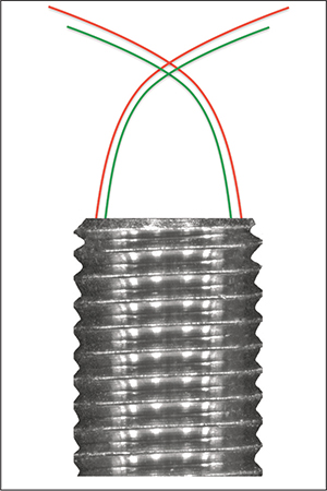
Fig. 5—A macro in an Excel spreadsheet automatically generates a mirror image of the original ON and OFF lines as a double-fish pattern. This indicates how the sensor should be positioned during production.